Weldable, crack-resistant co-based alloy and overlay method
a co-based alloy and crack-resistant technology, applied in the field of co-based alloys, can solve the problems of reducing the efficacy of these alloying elements by forming carbides, reducing the overall hardness of the alloy, so as to achieve sufficient ductility and improve corrosion and wear resistance. , the effect of improving the hardness
- Summary
- Abstract
- Description
- Claims
- Application Information
AI Technical Summary
Benefits of technology
Problems solved by technology
Method used
Image
Examples
example 1
Forming a Weld Overlay on a Solid Rod
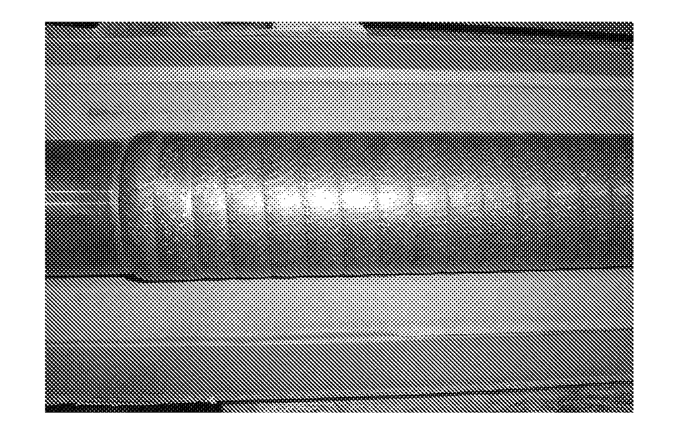
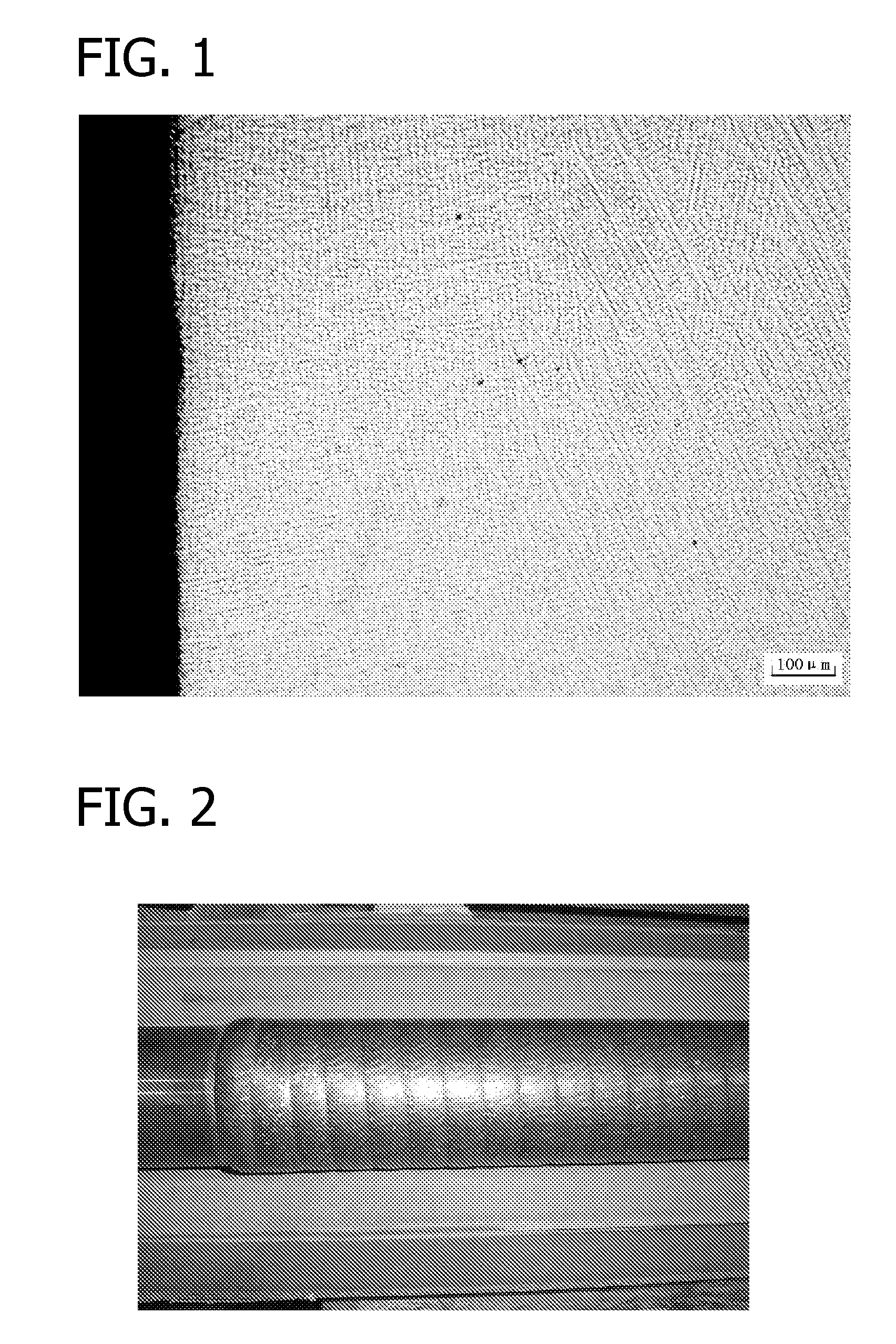
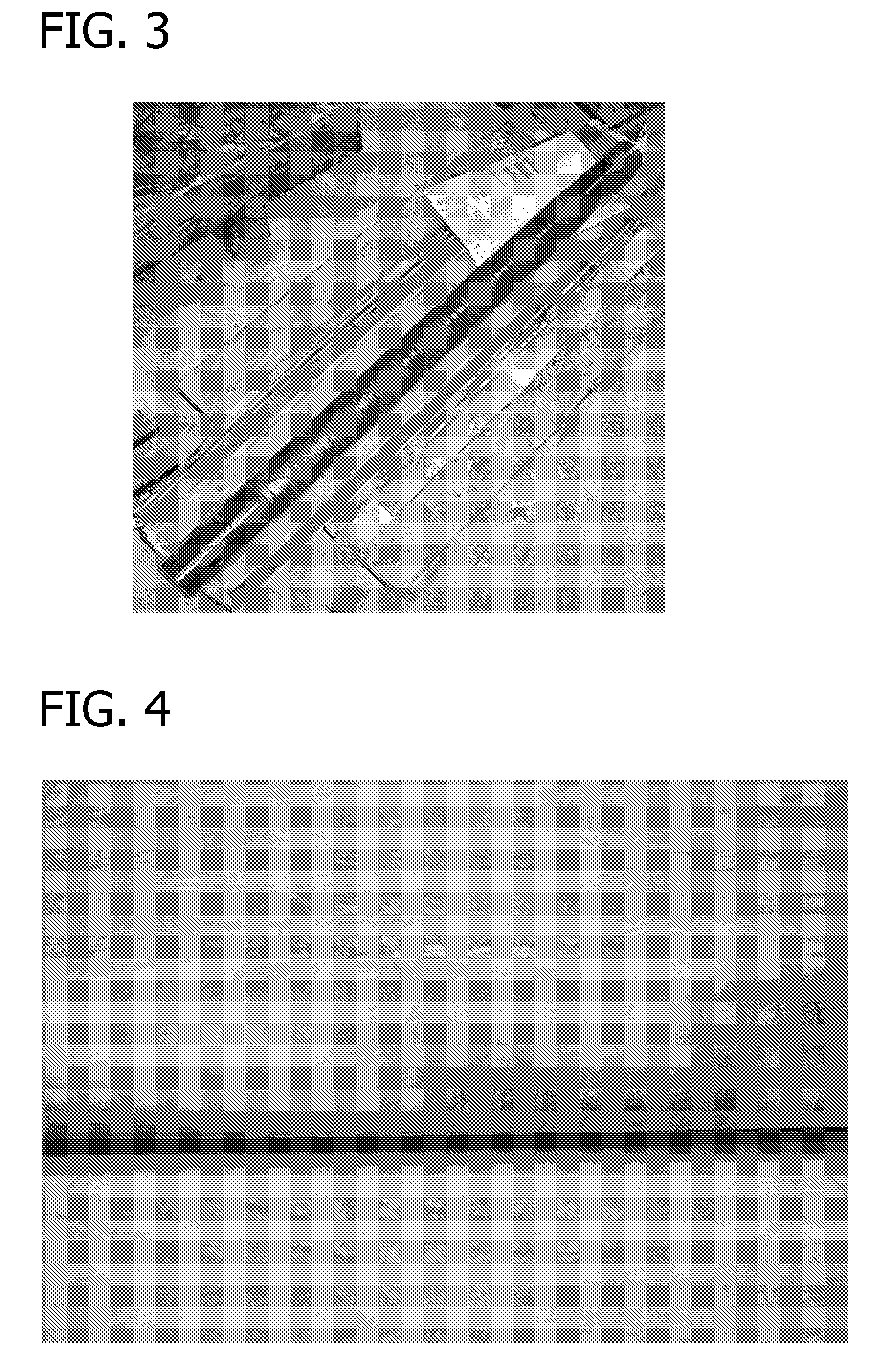
[0043]A powder comprising about 0.3 wt % C, 28 wt % Cr, 12 wt % Mo, 1.5 wt % Ni, 0 / 2 wt % Fe, and the balance Co was prepared using standard powder metallurgy techniques. The powder was then applied to a solid rod via PTA welding. The rod had a diameter of about 60 mm and a length of about 700 mm. FIGS. 2 and 3 show the rod with the alloy overlay thereon.
[0044]The alloy overlay's hardness was subjected to a standard Vicker's hardness test and found to be 440 HV. Further, no cracks in the overlay were observed using a standard dye penetrant test specified in ASTM E165-02, “Standard Test Method for Liquid Penetrant Examination.” A photograph of the overlay surface is shown in FIG. 4.
example 2
Comparison of Physical and Chemical Properties
[0045]Three samples were formed using conventional casting techniques and tested to compare the physical and chemical properties of the alloy of this invention with other known alloys. Their compositions are given in the table below, with Sample A from Example 1 being the alloy of this invention, Sample B being an existing commercial alloy sold under the name Stellite 21, and Sample C being an existing commercial alloy sold under the name Ultimet.
CrMoCSiNiWFeSample A28120.30.51.5—0.2Sample B285.50.31.53.0—0.5Sample C265.50.061.09.02.03.0
[0046]To compare the corrosion resistance between Samples A and B, cast specimens were tested at room temperature for 72 hours under ASTM G31 corrosion testing method. This test showed no measurable loss of mass for Sample A, whereas Sample B suffered loss at a rate of 0.89 mm per year.
[0047]To compare the wear resistance between the three samples, a sliding wear test was conducted on a pin-on-disc tribom...
example 3
[0048]The microstructure of a cast specimen of the invention's alloy having the composition of Sample A from Example 2 was examined. A back scattered electron image of the alloy is shown in FIG. 7. Analysis revealed a microstructure consisting of solid solution dendrites (dark areas) and eutectic regions (light areas) without primary carbide particles. The light eutectic regions indicate that they are rich in heavy elements, e.g., molybdenum. Since the specimen was cast, the microstructure is the result of slow cooling. With PTA welding, the overlay is usually cooled at a faster rate, creating a finer microstructure, e.g., FIG. 1.
PUM
| Property | Measurement | Unit |
|---|---|---|
| thickness | aaaaa | aaaaa |
| thickness | aaaaa | aaaaa |
| surface area | aaaaa | aaaaa |
Abstract
Description
Claims
Application Information
 - R&D
- Intellectual Property
- Life Sciences
- Materials
- Tech Scout
- Unparalleled Data Quality
- Higher Quality Content
- 60% Fewer Hallucinations
Browse by: Latest US Patents, China's latest patents, Technical Efficacy Thesaurus, Application Domain, Technology Topic, Popular Technical Reports.
© 2025 PatSnap. All rights reserved.Legal|Privacy policy|Modern Slavery Act Transparency Statement|Sitemap|About US| Contact US: help@patsnap.com


