Thermally stable cocurrent gasification system and associated methods

a gasification system and cocurrent technology, applied in the field of gasification apparatus, can solve the problems of increasing the downtime and operating cost of the gasifier, the oxidation and cracking of the pyrolysis gas, and the low gas residence time within the bed and the capital cost of the system, so as to reduce the amount of solid waste

Inactive Publication Date: 2008-08-21
ENERGY & ENVIRONMENTAL RES CENT FOUNDATIO
View PDF3 Cites 52 Cited by
  • Summary
  • Abstract
  • Description
  • Claims
  • Application Information

AI Technical Summary

Benefits of technology

[0011]Another embodiment of the invention provides a method of reducing solid waste that is capable of generating toxic emissions in synthetic gas produced by a gasification reactor having a gasification zone, the method including gasifying the solid waste in the gasification zone of the gasification reactor, oxidizing synthetic gas produced by the gasification reactor using a combustor to decompose toxic emissions in the synthetic gas, and using the combustor to convert chemical energy from synthesis gas to thermal energy to provide heat to the gasification reactor.

Problems solved by technology

The drawbacks to this type of gasifier are the low gas residence times within the bed and the capital cost of the system.
However, since the pyrolysis reactions occur toward the top, near the gas exit, a large portion of pyrolysis gases do not react inside the gasifier, producing a high-tar-content producer gas.
This oxidizes and cracks the pyrolysis gases.
A practical limitation of employing a packed bed is that the feed material traveling through the gasifier often bridges before reaching the reaction zones.
This usually requires the gasifier to be shut down and the bridge manually broken, increasing both downtime and operating cost of these gasifiers.
However, in reality, channeling within the bed, heat losses, and cooler wall temperatures within the gasifier allow some tars (pyrolysis gases) to pass through the relatively narrow, high-temperature combustion zone uncracked.
Moisture in the feed will also adversely affect the tar output of the gasifier, since moisture acts as a heat sink and will reduce the overall temperature within the gasifier.
This reduces the efficiency of the gasifier and increases nitrogen dilution of the resultant synthesis gas.
Disadvantages include that they still produce enough tars to foul downstream systems, require low moisture feed to operate, and have a tendency to bridge within the gasifier, depending on feed material.
These disadvantages currently outweigh the advantages and have prevented wide-scale adoption of this technology in commercial applications.

Method used


Image

  • Thermally stable cocurrent gasification system and associated methods
  • Thermally stable cocurrent gasification system and associated methods
  • Thermally stable cocurrent gasification system and associated methods

Examples


Embodiment Construction

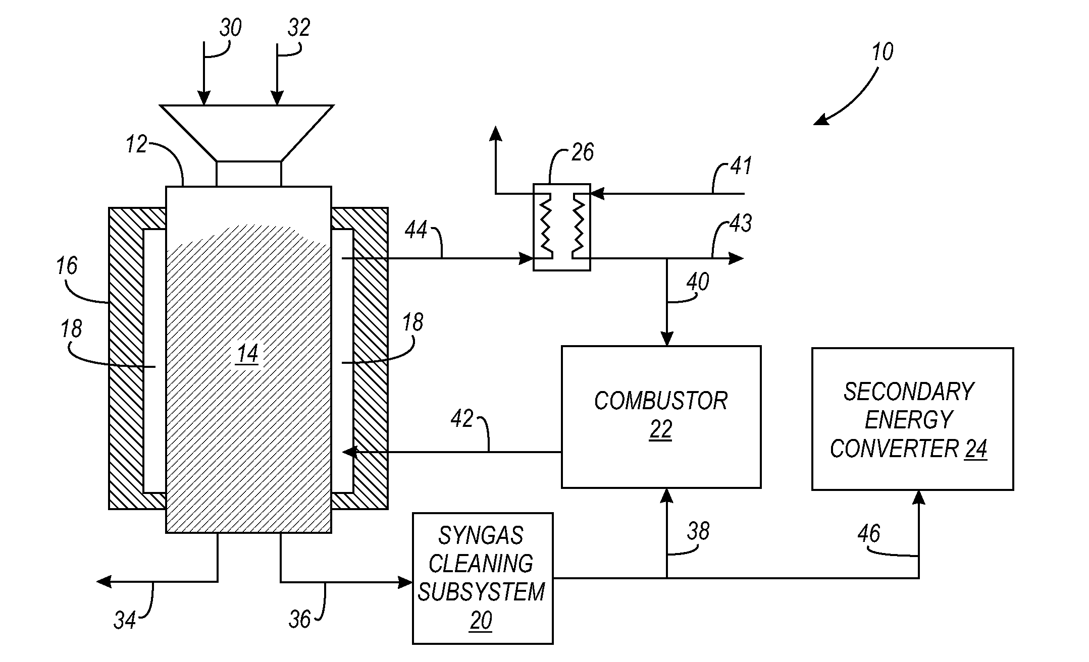
[0024]The present invention overcomes the disadvantages in the prior art described above by maintaining a wide high-temperature heating zone along the length of a gasifier (described in detail below). The wide high-temperature heating zone is maintained by circulating or flowing hot combustible gases through an annular space around the hot zone of the reactor. This creates a quasi-isothermal temperature zone large enough to ensure much longer residence times of gases in the reaction zone of the reactor, particularly reduction zone. In one example, the minimum temperature is 800° C., but preferably greater than 900° C. The minimum residence time is dictated by the feed, temperature, and moisture conditions within the gasifier and is essentially the residence time necessary to achieve near-total destruction of tars and conversion of char. The long temperature zone prevents channeling of pyrolysis gases and eliminates cold spots below 800° C. The hot space around the reactor minimizes ...


PUM

PropertyMeasurementUnit
temperatureaaaaaaaaaa
isothermal temperatureaaaaaaaaaa
temperatureaaaaaaaaaa

Abstract

A method and apparatus, in one example, relates to a system and method for the generation of very low-tar, high-energy synthesis gas from a large variety of carbonaceous feedstock, including those with higher moisture levels than conventional gasifiers. The system comprises a gasification reactor wherein a portion of the energy of the output syngas of the reactor is used to heat the gasification zone of the reactor via an annular space surrounding the gasification zone of the gasifier, to maintain a temperature condition above 800° C. The maintenance of a long, quasi-uniform high-temperature gasification zone reduces the amount of input air or oxygen, reduces bridging within the gasifier, cracks pyrolysis oils, increases the conversion of char, minimizes heat losses from the bed, and converts moisture within the packed bed into a gasification medium. This results in a very low tar synthesis gas with less nitrogen dilution and higher energy content than conventional gasifiers. The reduction in bridging reduces operating costs.

Description

CROSS REFERENCE TO RELATED APPLICATIONS[0001]This application claims priority under 35 U.S.C. § 119 to co-pending, commonly owned U.S. provisional patent application Ser. No. 60 / 890,884 filed on Feb. 21, 2007, entitled “THERMALLY STABLE COCURRENT GASIFICATION SYSTEM”, which is incorporated by reference herein.FIELD OF THE INVENTION[0002]The present invention relates to a gasification apparatus for producing high-caloric combustible gases with low tar content.BACKGROUND OF THE INVENTION[0003]Gasification technology development dates back to the early 1880s. In its simplest form, gasification of any solid carbonaceous fuel occurs through partial or substochrometaic oxidation of the fuel. Partial oxidation is the limited addition of oxygen to the fuel at elevated temperatures. This causes partial combustion of the fuel, which releases heat and the gaseous products H2O and CO2. The heat pyrolizes fuel, releasing volatiles, evaporates moisture, and provides the energy for the endothermic...

Claims


Application Information

Patent Timeline
Patent Type & Authority Applications(United States)
IPC IPC(8): C10J3/10
CPCC10J3/10C10J3/26C10J2300/0956C10J2300/0959C10J2300/1876C10J2300/1246C10J2300/1606C10J2300/165C10J2300/1659C10J2300/0973
Inventor HUTTON, PHILPATEL, NIKHIL
Owner ENERGY & ENVIRONMENTAL RES CENT FOUNDATIO
Why Eureka
Try Eureka