Capacitive deionization system for water treatment

a deionization system and water treatment technology, applied in the field of water purification, can solve the problems of increasing costs, secondary pollution, and the opportunity of reducing electric energy and recovering useful ions

Inactive Publication Date: 2008-08-21
SHIUE LIH REN
View PDF15 Cites 46 Cited by
  • Summary
  • Abstract
  • Description
  • Claims
  • Application Information

AI Technical Summary

Benefits of technology

[0015]The present invention provides a method for regenerating FTC electrodes, wherein supercapacitors are used for rapidly regenerating the FTC electrodes. First, the energy of the FTC electrodes is discharged to the supercapacitors, which serve as a reservoir to store the energy discharged by the saturated FTC electrodes. Next, the residual energy of FTC electrodes is exchanged between FTC modules and supercapacitors together with the circulation of rinsing water. During the regeneration process, the polarities of the electrodes of FTC modules are reversed periodically so that the residual energies of FTC modules and supercapacitor can charge and discharge to each other such that the residual energy of FTC modules is consumed by a series of minor electric shorts. Meanwhile, the adsorbed ions are removed from the surface of the FTC electrodes and carried away by the rinsing water. As a result, the FTC modules is regenerated and suitable for reuse treat the waters.

Problems solved by technology

From pretreatment of water to maintenance of the equipments, all of the aforementioned water purification techniques utilize one or many kinds of chemicals resulting in secondary pollution and increase cost.
Furthermore, the capability of discharging the saturated electrodes presents the opportunities of reducing the electric energy and recover useful ions.
Compared with RO and ion-exchange, CDI is a relatively new and significantly unknown for capability of reducing TDS of water, and therefore the CDI technique is far less explored by the academies or industries compared to RO, ion exchange and electrodialysis techniques.
As disclosed in '718, a low DC voltage is applied to each electrode pair, and the electrical connection is complex and expensive.
Though the electrical connection is greatly simplified in '935, the cylindrical FTC suffers cross contamination, particularly, from treating highly concentrated water, for example, seawater.
Consequently, the output of the CDI operation is severely impaired due to the significant loss of ion-adsorption capability of FTC.
Due to the close and tight enclosure of FTC, water is prone to be trapped in the roll causing serious cross contamination during the CDI operation.
In the perspective of CDI technique, '378 is disadvantageous in using RuO2.xH2O as the ion-adsorption material and the edges of electrodes are not sealed.
Though RuO2.xH2O has a high energy density for making supercapacitor as an energy-storage device, the energy capacity of the expensive material is derived from surface reduction-oxidation reaction that is of no use for the CDI operation wherein only ion-adsorption is needed.
Furthermore, the exposed edges of the electrodes may allow water to bypass without being treated, also current to leak around the edges cause ohmic heating and other damages.

Method used


Image

  • Capacitive deionization system for water treatment
  • Capacitive deionization system for water treatment
  • Capacitive deionization system for water treatment

Examples


example 1

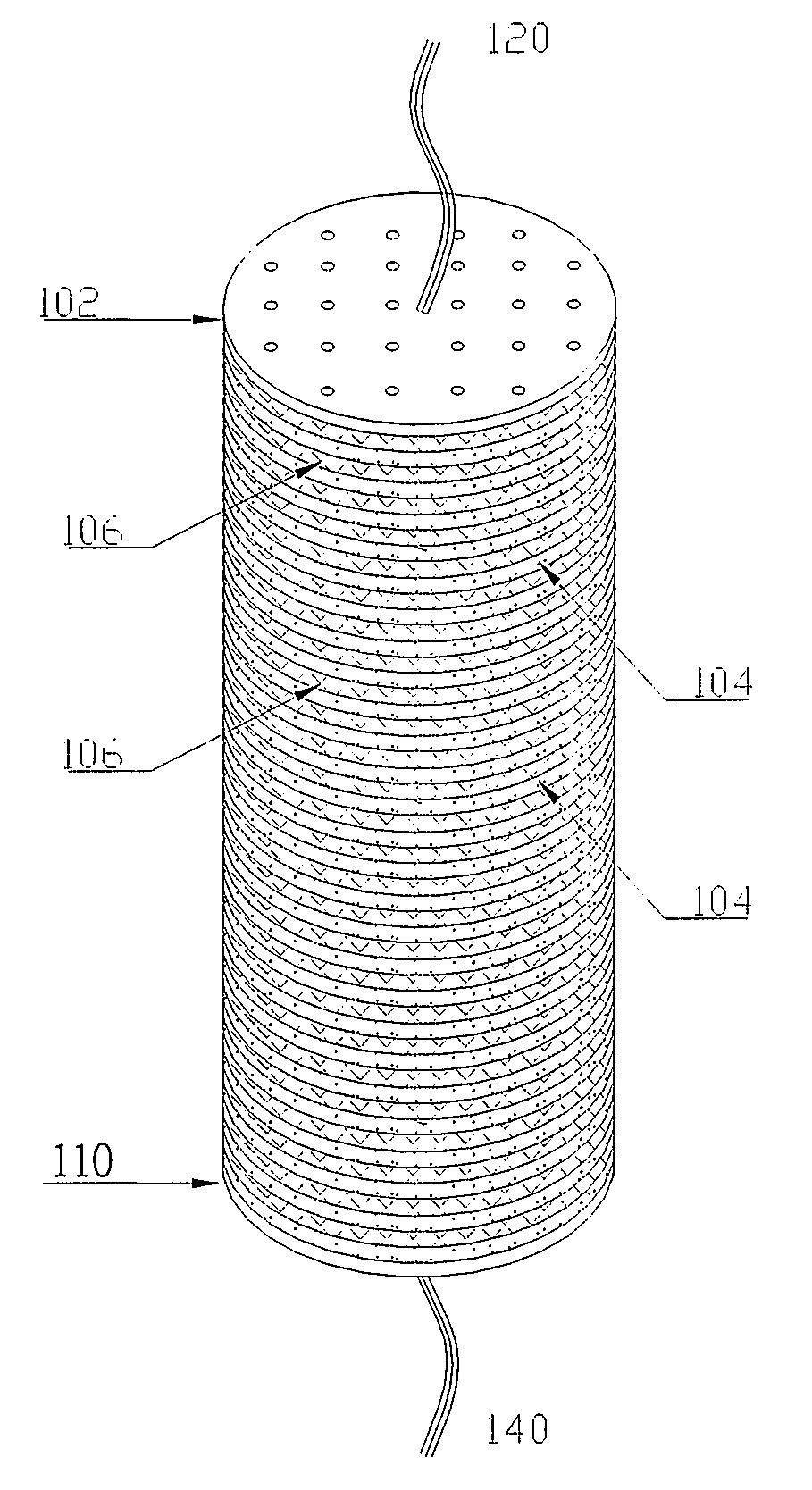
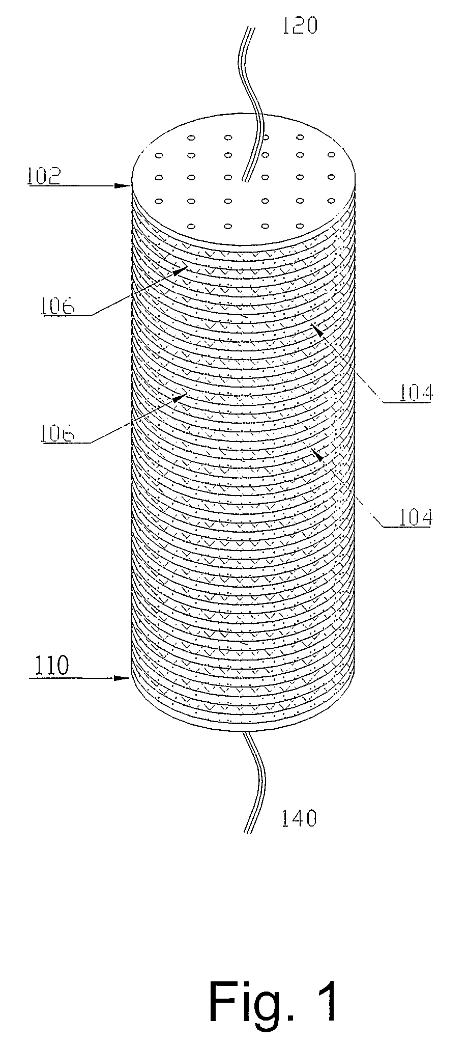
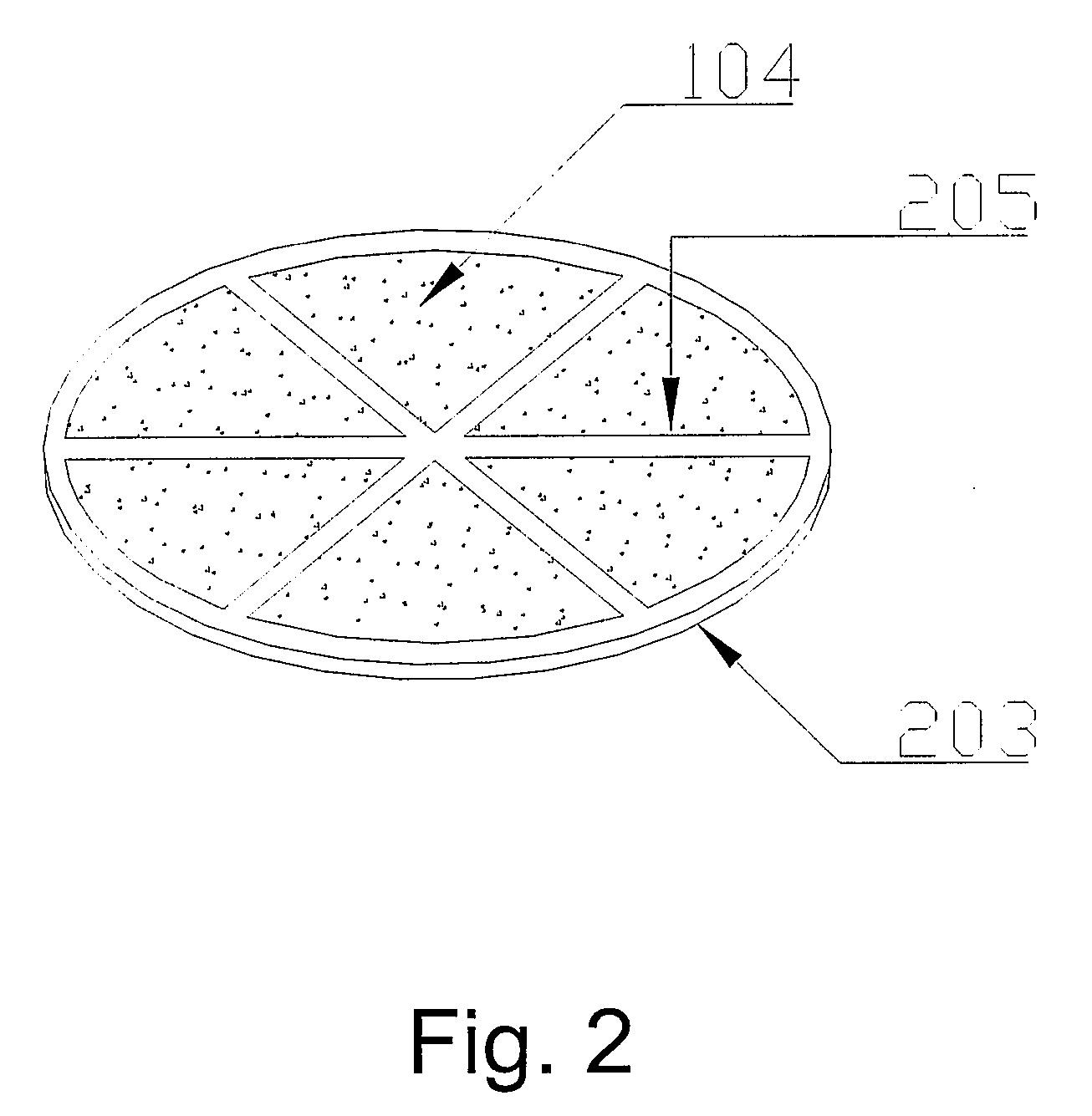
[0033]A FTC module 100 comprising 2 end electrodes 102 and 110 and 20 FTC electrodes 104 stacked between the two end electrodes as shown in FIG. 2 was used. Each FTC electrode 104 has a circular shape having a diameter of about 54 mm. Tap water was passed through the FTC module for removing the ions such as Mg2+ and Ca2+, from the water. Both of the end electrodes 102 and 110 were comprised of stainless steel disks coated with activated carbon and have the same diameter as that of the FTC electrodes 104. The end electrodes 102 and 110 were welded to a metal rod having 2 mm diameter, for compressing the FTC electrodes 104 between the two end electrodes 102 and 110 and for serving as the terminal for connecting to a power supply. The FTC electrodes 104 may be comprised of commercial carbon cloths made of activated carbon and fabrics having a bulk conductivity of 0.001 S / cm. The sealing members and the FTC electrodes 104 were stacked alternately such that a gap of about 1 mm was mainta...

example 2

[0038]A system comprising five FTC modules 100 was used for treating water, wherein each FTC module 100 comprises the configuration of the FTC module 100 used in EXAMPLE 1. The FTC modules 100 are connected in series and are used for desalination of seawater. Though the five modules are connected in series for water flow, they are charged in parallel by applying a voltage, of about 35 V DC. 1 liter of filtered seawater with TDS of about 35,000 ppm was delivered at a rate of 50 ml / min through the FTC modules 100 in one pass. During the charging period, the working current is registered as 3 A, and the TDS of the treated water was measured and was found to be reduced to 2500 ppm in one-pass treatment.

[0039]A group of supercapacitor modules comprising three supercapacitors were used for regenerating the FTC modules 100. Each supercapacitor has a specification of 30 V×20 F, and are connected in series to form a pack of 90 V×6.7 F and serve as an energy-reservoir for the regeneration of ...


PUM


Abstract

A capacitive deionization (CDI) system for deionizing water is disclosed. The CDI system comprises at least a flow through capacitor (FTC) module, at least a first supercapacitor, at least a second supercapacitor, at least a third supercapacitor and a controller. The FTC module comprises a plurality electrodes for removing ions from water flowing between the electrodes under an electric field applied between the electrodes. The first supercapacitor is connected between the potential source and the FTC module for amplifying energy provided by the potential source. The second supercapacitor is connected to the FTC module for receiving energy from the FTC module for regenerating the electrodes of the FTC module. The third supercapacitor is adapted for exchanging energy with the FTC module for regenerating the electrodes of the FTC module. The controller is adapted for regulating deionization rate of the water and regeneration of the electrodes of the FTC module.

Description

BACKGROUND OF THE INVENTION[0001]1. Field of the Invention[0002]The present invention generally relates to water purification. More particularly, the present invention relates to a capacitive deionization system for deionizing water.[0003]2. Background of the Related Art[0004]Water purification may be implemented by a variety of techniques, such as, reverse osmosis (RO), ion exchange or electrodialysis just to name few. With increasing environment protection awareness, an ideal water purification technique should be cost effective and pollution free in addition to reliability of the water purification technique. From pretreatment of water to maintenance of the equipments, all of the aforementioned water purification techniques utilize one or many kinds of chemicals resulting in secondary pollution and increase cost. Capacitive deionization (CDI) technique, which solely depends on electricity for performing water treatment and also for maintaining the equipment, presents an environme...

Claims


Application Information

Patent Timeline
Patent Type & Authority Applications(United States)
IPC IPC(8): H01G9/00
CPCC02F1/46104C02F1/4691C02F2001/46133C02F2201/46165C02F2001/46157C02F2103/08C02F2001/46138Y02W10/37
Inventor SHIUE, LIH-RENCHEN, MU-FACHENG, CHUN-SHENCHEN, YI-SHUOCHANG, YU-CHUNGOTO, MASAMI
Owner SHIUE LIH REN
Why Eureka
Try Eureka