Electrochemical supercapacitor/lead-acid battery hybrid electrical energy storage device

a supercapacitor and lead acid battery technology, applied in capacitor collector combinations, electrochemical generators, transportation and packaging, etc., can solve the problems of limiting the scope of application, limiting the use range of the supercapacitor, and even the best of such supercapacitors are burdened with low specific energy parameters and high cost, so as to achieve the effect of low cost and substantial reduction of the cost of the hybrid device of the present invention

Inactive Publication Date: 2008-08-21
UNIVERSAL SUPERCAPACITORS LLC
View PDF41 Cites 65 Cited by
  • Summary
  • Abstract
  • Description
  • Claims
  • Application Information

AI Technical Summary

Benefits of technology

[0016]A heterogeneous electrochemical supercapacitor/lead-acid battery (i.e., “hybrid”) device of the present invention overcomes the drawbacks described above with respect to known lead-acid battery/supercapacitor systems. Further, in contrast to the aforementioned lithium-ion battery/supercapacitor type hybrid device, the cost of a hybrid device of the present invention is...

Problems solved by technology

Unfortunately most of these modern supercapacitors are also burdened with low specific energy parameters and high cost.
Despite the fact that the technology of manufacture and the overall performance characteristics of modern supercapacitors continues to improve, the cost of storing energy using even the best of such supercapacitors is quite high in comparison with the cost of storing energy using modern batteries.
Consequently, the negative characteristics of supercapacitors typically limit the scope of their application to situations where high discharge power is paramount.
However, along with a decrease in electrode and separator thickness, comes an increase in the cost of energy storage.
Additionally, the service and cycle life of such batteries are generally substantially reduced.
Batteries with thin electrodes also require precision modes of charge and considerable operational maintenance.
The internal resistance of a battery at a low-level state of charge has an increased value in comparison to the internal resistance of a fully charged battery, and this characteristic limits the power parameters of partially discharged batteries.
Such behavior manifests itself to the greatest extent when lead-acid batteries are operated in low temperature environments and, consequently, considerably limits the scope of their application.
Due to electrode self-discharge, another drawback of lead-acid batteries is sulfation of the near-surface layer of their negative electrodes during storage in a fully charged state—which may occur even when such batteries a...

Method used


Image

  • Electrochemical supercapacitor/lead-acid battery hybrid electrical energy storage device
  • Electrochemical supercapacitor/lead-acid battery hybrid electrical energy storage device
  • Electrochemical supercapacitor/lead-acid battery hybrid electrical energy storage device

Examples


specific examples

Example 1

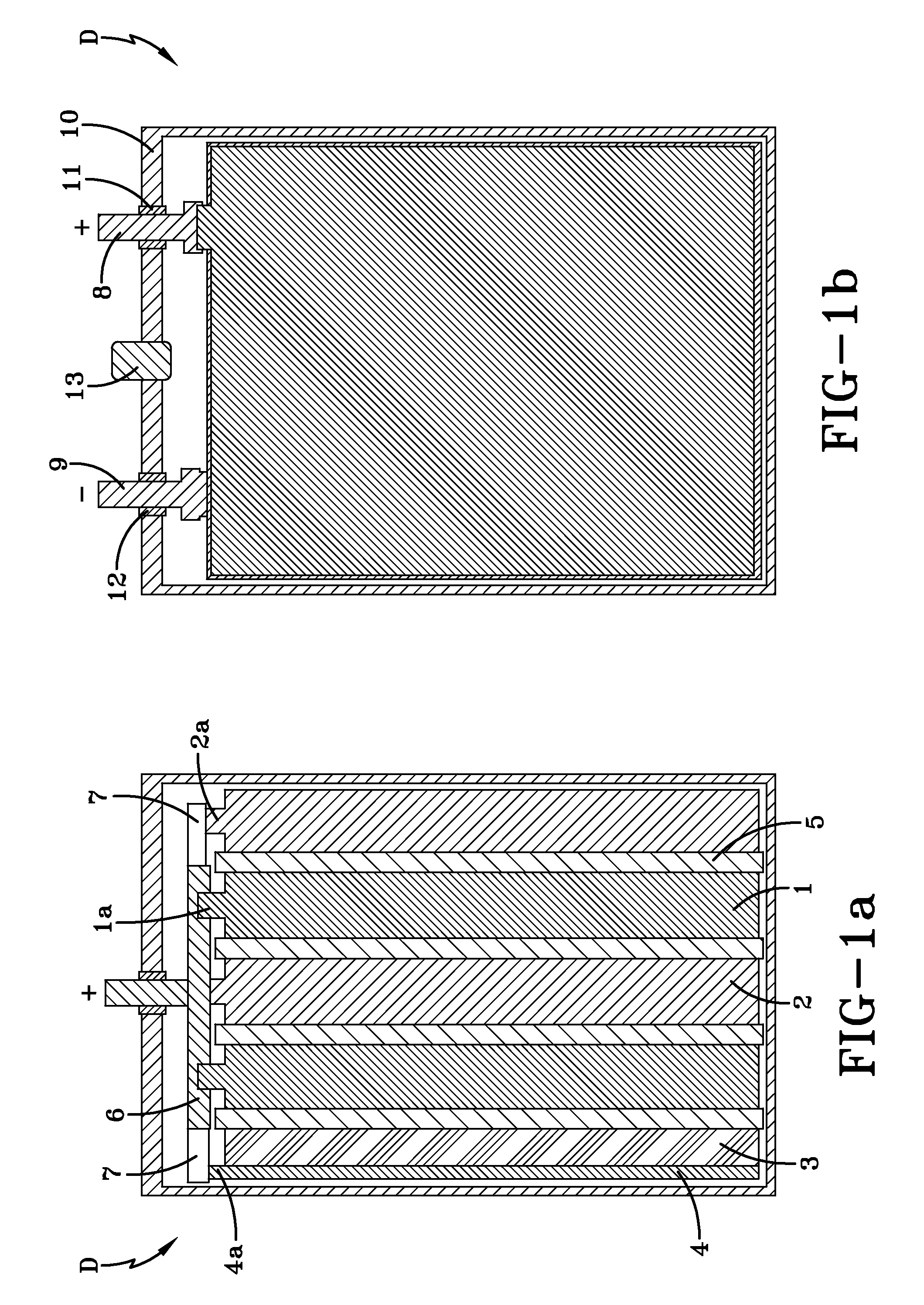
[0052]In order to check the serviceability and identify the power and energy parameters of a hybrid device according to the present invention, a hybrid device HD#1 was manufactured in the form set forth in FIGS. 1a-1b. The hybrid device HD#1 includes two positive electrode plates 1 made of PbO2, with approximate overall dimensions of 135 mm×72 mm×1.4 mm; two spongy lead negative electrode plates 2 with approximate overall dimensions of 135 mm×72 mm×1.8 mm; and one polarizable carbon negative electrode plate 3 with a mass density of 0.56 g / cm3, a specific electric capacitance of 620 F / g, a specific electric resistance of 2.6 Ohm·cm and approximate overall dimensions of 135 mm×72 mm×2 mm. The concentrations of Fe and Mn admixture atoms in the polarizable carbon negative electrode plate were determined to be about 56 ppm and 175 ppm, respectively. The hybrid device HD#1 also includes a current collector 4 associated with the polarizable carbon negative electrode 3. In this exe...

example 2

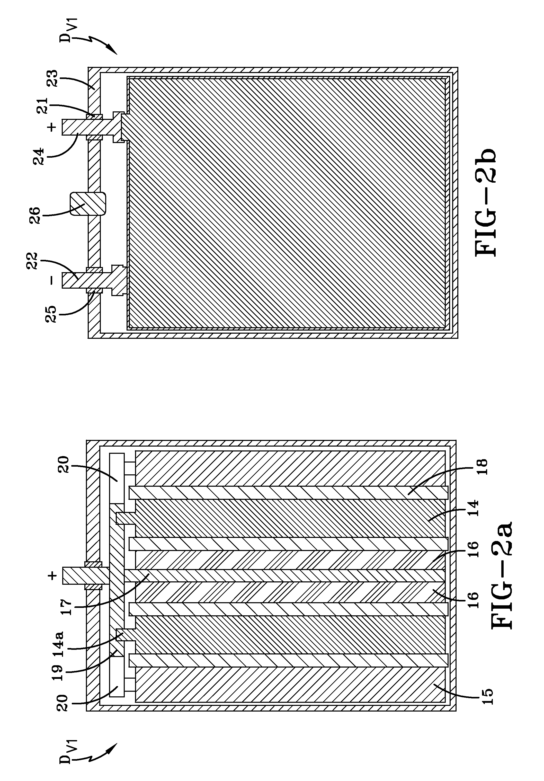
[0067]A hybrid device HD#2 was manufactured as shown in FIGS. 2a-2b. The hybrid device HD#2 includes two positive electrode plates 14 made of PbO2, with overall dimensions of approximately 135 mm×72 mm×1.4 mm; two spongy lead negative electrode plates 15 with overall dimensions of approximately 135 mm×72 mm×1.8 mm; and two polarizable carbon negative electrode plates 16 with a mass density of 0.65 g / cm3, a specific electric capacitance of 670 F / g, a specific electric resistance of 1.02 Ohm·cm and overall dimensions of approximately 135 mm×72 mm×1.2 mm. The concentrations of Fe and Mn admixture atoms in the polarizable carbon negative electrode plate were determined to be about 5 ppm and 14 ppm, respectively. The hybrid device HD#2 also includes a current collector 17 associated with the polarizable carbon negative electrodes 16. In this embodiment, the current collector 17 has overall dimensions of approximately 135 mm×72 mm×0.26 mm, and is made of lead alloy containing approximatel...

example 3

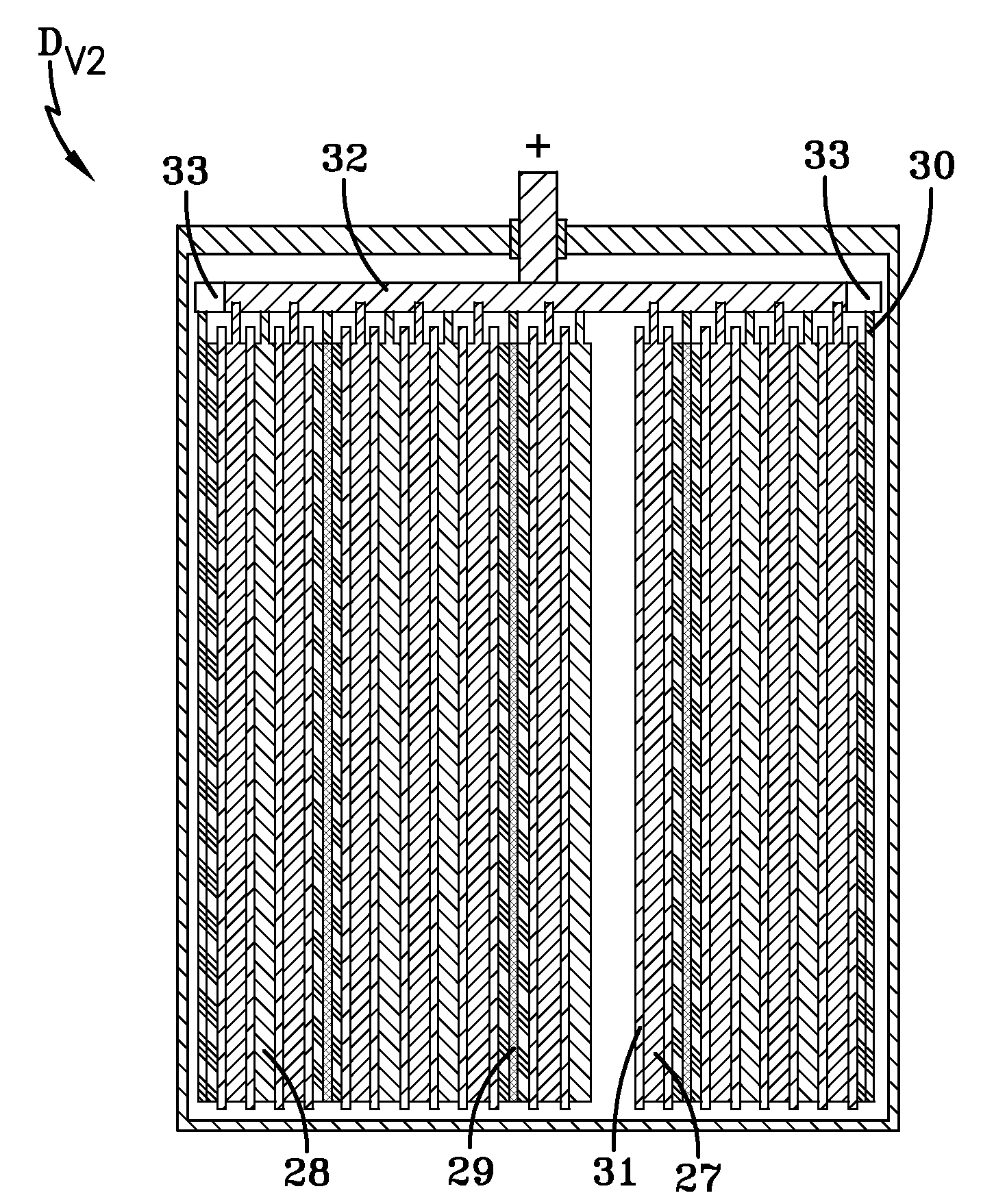
[0077]In order to research the influence of the concentration of Fe and Mn admixture atoms contained in the polarizable carbon negative electrode on the energy and power parameters and on the self-discharge of a hybrid device of the present invention, an additional exemplary hybrid device HD#3 was constructed. A difference between the design of this hybrid device HD#3 and the first exemplary hybrid device HD#1 shown in FIGS. 1a-1b is that the end spongy lead negative electrode of the first hybrid device is replaced by a polarizable carbon negative electrode. Thus, the hybrid device HD#3 includes two positive electrode plates of PbO2, one spongy lead negative electrode plate, and two polarizable carbon negative electrode plates. The electrodes of this hybrid device HD#3 have overall dimensions that are similar to the corresponding electrodes of the first hybrid device HD#1 as set forth in Example 1.

[0078]The mass density of the polarizable carbon negative electrodes is 0.52 g / cm3, th...


PUM


Abstract

A hybrid lead-acid battery/electrochemical capacitor electrical energy storage device. The lead-acid battery and electrochemical capacitor reside in the same case and are electrically connected. Preferably, a hybrid device of the present invention includes at least one non-polarizable positive electrode, at least one non-polarizable negative electrode, and at least one polarizable electric double layer negative electrode. Separators reside between the electrodes and the separators and electrodes are impregnated with an aqueous sulfuric acid electrolyte. A hybrid device of the present invention exhibits high power characteristics.

Description

BACKGROUND OF THE INVENTION[0001]The present invention is directed to a hybrid electrical energy storage device having both lead acid battery and electrochemical supercapacitor elements. More particularly, the present invention is directed to such a hybrid electrical energy storage device wherein the lead acid battery and electrochemical supercapacitor elements are disposed within the same case and are electrically connected.[0002]The current pace of development of many advanced technologies has placed increased requirements on the operational parameters of various chemical power sources that are commonly used therein. To comply with these increased requirements, the operating parameters of current chemical power sources have been continuously improved. Much of this improvement has occurred in the areas of design and technology of manufacture. As a result, new power sources have been developed that offer improved technical and operational parameters.[0003]Nonetheless, further enhanc...

Claims


Application Information

Patent Timeline
IPC IPC(8): H01M16/00
CPCH01G9/058H01G9/14H01G9/155H01G11/38Y02T10/7022H01M12/005Y02E60/126Y02E60/13H01M4/14H01G11/08H01G11/04H01G11/18H01G11/10H01G11/82Y02T10/70Y02E60/10H01G11/46H01G11/22H01G11/58
Inventor KAZARYAN, SAMVEL AVAKOVICHKHARISOV, GAMIR GALIEVICHKAZAROV, VLADIMIR ALEXANDROVICHRAZUMOV, SERGEY NIKOLAEVICHLITVINENKO, SERGEY VITALIEVICH
Owner UNIVERSAL SUPERCAPACITORS LLC
Why Eureka
Try Eureka