Nanofilament Scaffold for Tissue Regeneration

a tissue regeneration and nano-filament technology, applied in the field of tissue engineering, can solve the problems of lack of co-adaptation, gap between two nerve stumps, and limited use of autografts

Active Publication Date: 2008-08-28
GEORGIA TECH RES CORP
View PDF25 Cites 145 Cited by
  • Summary
  • Abstract
  • Description
  • Claims
  • Application Information

AI Technical Summary

Benefits of technology

[0008]An improved scaffold for tissue regeneration has been developed. In one aspect, a scaffold is provided that includes a structure comprising a plurality of uniaxially oriented nanofibers made of at least one synthetic polymer. In a preferred embodiment, at least 75% of the nanofibers are oriented within 20 degrees of the uniaxial orientation. In one embodiment, the nanofibers have a diameter between about 400 nm and about 1000 nm. In a preferred embodiment, the tissue scaffold is implantable scaffold and the structure comprises two or more stacked layers of the uniaxially oriented nanofibers, the layers being oriented such that the nanofiber orientation of among the layers is substantially identical. In one embodiment, the structure further includes at least one spacer between layers of uniaxially oriented nanofibers in the stacked layers. In one case, the spacer has a thickness between 50 and 250 μm. The space may include a hydrogel, polyethylene glycol, agarose, alginate, polyvinyl alcohol, collagen, Matrigel, chitosan, gelatin, or a combination thereof. For example, the structure may include alternating layers of oriented nanofibers and layers of hydrogel. In one embodiment, the implantable scaffold further includes a tubular conduit in which the structure is disposed.

Problems solved by technology

Severe traumatic injury or invasive surgical procedures on a peripheral nerve can result in a gap between two nerve stumps.
However, the use of autografts is limited by the inadequate availability of nerves to use in the autograft (IJkema-Paassen, et al., Biomaterials 25:1583-92 (2004)), the lack of co-adaptation between the injured nerve and the nerve graft due to size / length / modality mismatch (Nichols, et al., Exp. Neurol. 190:347-55 (2004)), and functional loss at the donor sites (Bini, et al., J. Biomed. Mater. Res A 68:286-95 (2004)).
However, these approaches are limited in their ability to enable regeneration across long nerve gaps, and have been unsuccessful in promoting regeneration across gaps longer than 15 mm in rodents.

Method used


Image

  • Nanofilament Scaffold for Tissue Regeneration
  • Nanofilament Scaffold for Tissue Regeneration
  • Nanofilament Scaffold for Tissue Regeneration

Examples


example 1

Method of Making Oriented Nanofiber Films by Electrospinning

[0044]Uniaxially oriented nanofiber films were fabricated by electrospinning poly (acrylonitrile-co-methylacrylate, random copolymer, 4 mole percent of methacrylate) (PAN-MA) on a high speed rotating metal drum. An 18% (w / v) PAN-MA solution was prepared in an organic solvent, N,N-Dimethyl Formamide (DMF) at 60° C. The polymer solution was loaded into a 10 mL syringe and delivered at a constant flow rate (1 mL / hour) to a 21 gauge metal needle connected to a high voltage power supply. Upon applying a high voltage power supply of about 13 kV to about 18 kV, a fine jet of polymer solution was ejected from the needle and deposited on a thick aluminum foil wrapped around the high speed rotating metal drum. The foil carrying the aligned electrospun nanofiber film was then removed and stored at room temperature. The nanofiber film was approximately 10 μm thick and composed of nanofibers with diameters in the range of about 400 nm t...

example 2

Three-Dimensional Oriented Nanofiber Scaffold

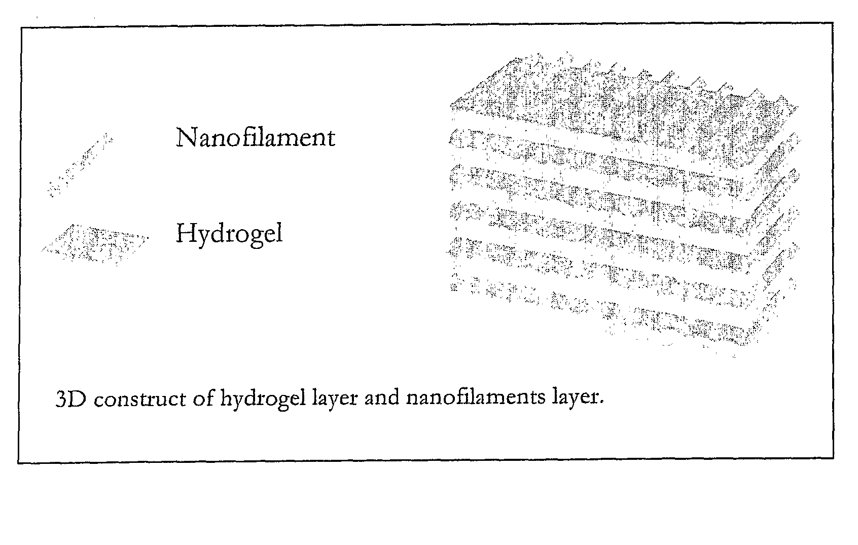
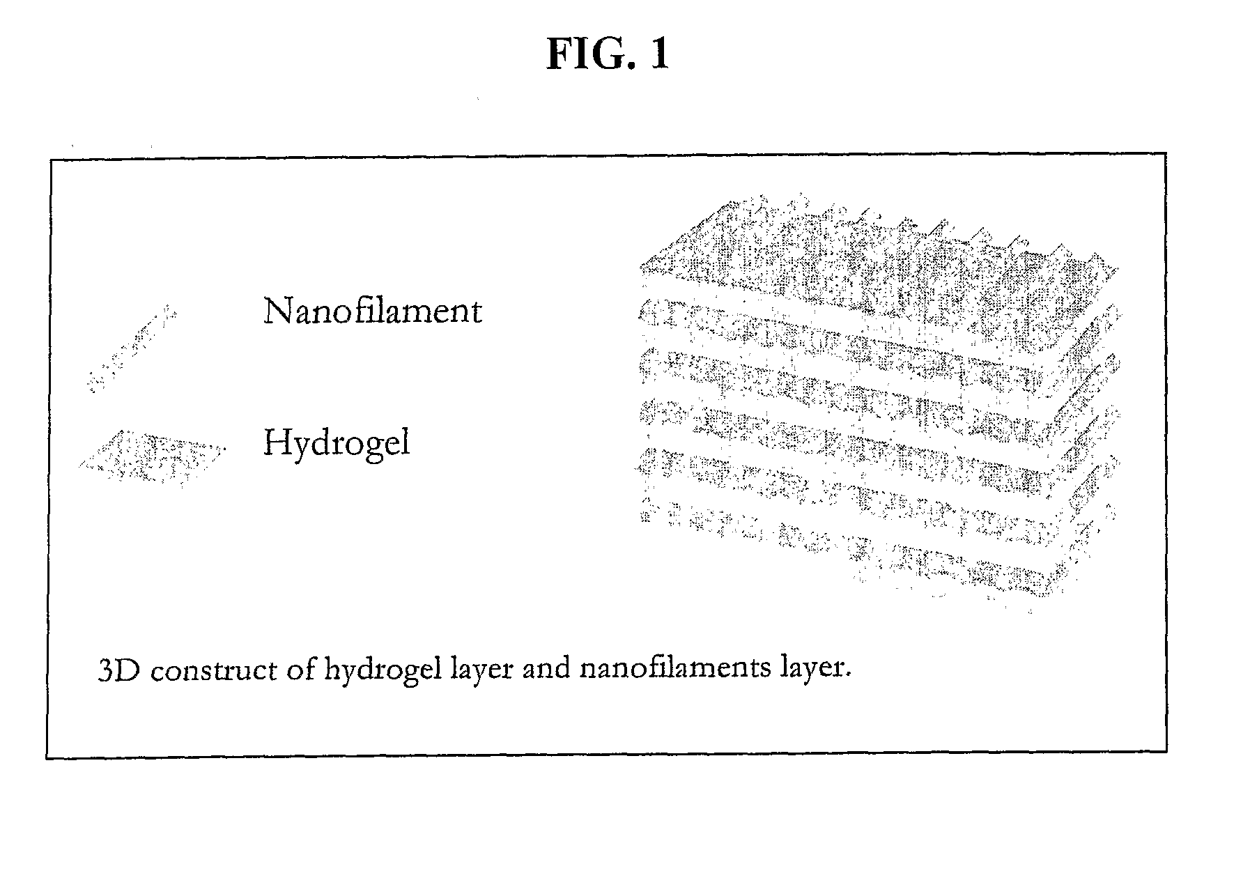
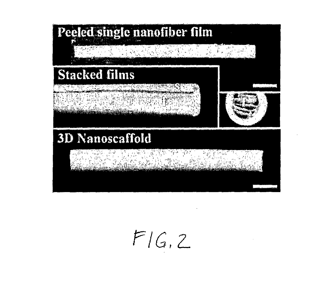
[0045]An oriented, 3-D nanofiber scaffold was created by stacking the uniaxially oriented nanofiber films made as described in Example 1. A total of 15 nanofiber films were cut into 17 mm×1 mm pieces, removed from the aluminum foil, and stacked so that the orientation of the nanofibers aligned with the axis of regeneration within two halves of a longitudinally split polysulfone nerve conduit (Koch Membrane Systems, 50,000 MW cutoff—19 mm long, 1.5 mm inner diameter). The longitudinal half-cut was closed and sealed using UV light curing adhesive. See FIG. 4. The nanofiber scaffold was sterilized by soaking it in a 70% ethanol solution for 30 minutes and washing it three times with sterilized deionized water. The nanofiber scaffold was stored in sterilized PBS until implantation. FIG. 2 shows representative photograph of a single nanofiber film, stacked films, and a three-dimensional nanofiber scaffold.

example 3

In Vivo Nerve Tissue Growth Using Oriented, 3-D Nanofiber Scaffold

[0046]The nanofiber scaffolds fabricated as described in Example 2 were implanted into a transected tibial nerve of adult male rats. Autograft implants and saline filled nerve conduit implants were also tested in comparator / control animals.

[0047]Double immunostaining (axons and Schwann cells) revealed that the implanted nanofiber scaffolds facilitated the regeneration of transected tibial nerves across 17 mm nerve gaps, and that host derived Schwann cells infiltrated the nanofiber scaffolds from both proximal and distal stumps of the nerve. The transected axons entered into the proximal end of the nanofiber scaffolds, regenerated through entire length of the nanofiber scaffold along the nanofiber films, and moved into the distal stump of the nerve. This successful regeneration was observed in all nanofiber scaffold treated animals (n=12). The regenerating axons always co-localized with the aligned Schwann cells throug...


PUM

PropertyMeasurementUnit
diameteraaaaaaaaaa
diameteraaaaaaaaaa
thicknessaaaaaaaaaa

Abstract

A scaffold for tissue regeneration is provided. In a preferred embodiment, the scaffold is implantable in a patient in need of nerve or other tissue regeneration and includes a structure which has a plurality of uniaxially oriented nanofibers made of at least one synthetic polymer. Preferably, at least 75% of the nanofibers are oriented within 20 degrees of the uniaxial orientation. The scaffold beneficially provides directional cues for cell and tissue regeneration, presumably by mimicking the natural strategy using filamentous structures during development and regeneration.

Description

CROSS REFERENCE TO RELATED APPLICATIONS[0001]This application claims benefit of U.S. Provisional Application No. 60 / 659,218, filed Mar. 7, 2005. That application is incorporated herein by reference in its entirety.STATEMENT REGARDING FEDERALLY SPONSORED RESEARCH OR DEVELOPMENT[0002]This invention was made with U.S. government support under Contract No. EEC-9731643 awarded by the National Science Foundation and under Contract No. R01NS044409-02 awarded by the National Institutes of Health. The U.S. government has certain rights in the invention.BACKGROUND OF THE INVENTION[0003]This invention is generally in the field of tissue engineering, and more particularly pertains to synthetic scaffold materials and methods useful in directing tissue growth in vivo or ex vivo.[0004]Severe traumatic injury or invasive surgical procedures on a peripheral nerve can result in a gap between two nerve stumps. The clinical “gold standard” for bridging peripheral nerve gaps is the use of autografts, ty...

Claims


Application Information

Patent Timeline
Patent Type & Authority Applications(United States)
IPC IPC(8): A61F2/08
CPCA61L27/16A61L27/18A61L27/48A61L27/52A61L2400/12C08L33/20C08L67/04
Inventor BELLAMKONDA, RAVI V.KIM, YOUNG-TAEKUMAR, SATISH
Owner GEORGIA TECH RES CORP
Why Eureka
Try Eureka