Automotive exhaust component and process of manufacture

a technology of exhaust components and manufacturing processes, applied in the direction of machines/engines, other domestic objects, separation processes, etc., can solve the problems of notoriously vulnerable loci of corrosive attack on the welding surface, and achieve the effect of reducing the diameter, greatly reducing the required press force at each stage, and being highly adaptabl

Inactive Publication Date: 2008-09-04
EVOLUTION IND INC
View PDF1 Cites 11 Cited by
  • Summary
  • Abstract
  • Description
  • Claims
  • Application Information

AI Technical Summary

Benefits of technology

[0023]Advantageously, the one-piece, seamless converter construction of the invention is economical to produce and eliminates welding of housing components that are highly prone to failure. More specifically, the one-piece, seamless construction of the converter housing reduces the size and number converter parts (as compared with known practical constructions) while, at the same time, increasing the converter's effectiveness and improving its construction and manufacture. The converter is inherently economical to produce and can be mass-manufactured in the large volumes required to supply original equipment converters directly to manufacturers of automobiles and trucks for factory installation in exhaust systems. Furthermore, the improvement of the housing affords additional advantages including better vehicle fuel efficiency and better manufacturing economics.
[0024]The elimination of any welding of seams or end caps afforded by the one-piece construction of the present catalytic converter greatly enhances its reliability during service. Welds are notoriously vulnerable as loci of corrosive attack due both to chemical and stress effects. In operation, catalytic converters in typical on-road vehicle applications are exposed externally to road salt and other corrosive substances and internally to acidic exhaust gases. The absence of weldments in the present catalytic converter removes a prime source of failures during the service life of the device.
[0026]Compared to other known methods used to form ends, swaging often affords a number of advantages. The reduction in diameter can be carried out in a sequence of steps using a plurality of dies. In some instances, a multi-step swaging process is desirable, because the needed deformation is too great to be attained practically using a single press operation. By swaging sequentially, the required press force at each stage is greatly reduced. As a result, the swaging process is highly adaptable, providing a designer with great flexibility in tailoring a housing to fit into an available space and in optimizing the dynamics of gas flow through the device. The tubulated ends and transition sections are smooth and substantially free of circumferential ridges on either the inside or outside surfaces. The external appearance of the device is enhanced. The smoothness of the inside surface and the absence of ridges thereon minimizes generation of turbulence that impedes the flow of exhaust gas through the converter and causes excessive backpressure. Swaging ordinarily maintains a level of ductility sufficient to allow the converter to be connected to the rest of the exhaust system by clamped, welded, or flanged joints.
[0027]A further benefit offered by some embodiments of the present process over spinning is the ability to form more intricate structures, including those having features such as extended length and bends or other non-symmetrical configuration. Since the present end-forming process does not entail rapid rotation of the workpiece, neither rotational balance nor the size of available lathes or similar machine tools is a consideration. End forming can thus produce converters having inlet and outlet ports and transitional sections which can be round or have a variety of other shapes, such as that of ovals, and especially “flat ovals”, needed to accommodate vehicle clearance or other size and space requirements. A converter could also be formed with bends in any of its sections. Designs can also be formed wherein the catalytic element is an oval cylinder instead of a right circular cylinder.
[0028]In one aspect of the invention the catalytic element comprises a frangible ceramic honeycomb structure having a plurality of passages extending therethrough. The surfaces of the passages are substantially covered with a finely dispersed, catalytically active substance. This construction makes effective use of the catalytic substance, which generally comprises one or more of the expensive platinum-group noble metals including Pd, Pt, and Rh. The ceramic honeycomb is preferably encircled with a mat of an intumescent material which acts to resiliently and insulatively secure it within the inside diameter of the intermediate section. The intumescence of the mat material creates a reliable and gas-tight seal that protects the ceramic during its construction and in-service life. In addition, the intumescent material forces the exhaust gas stream to pass through the passages of the honeycomb, maximizing catalytic efficacy.

Problems solved by technology

Welds are notoriously vulnerable as loci of corrosive attack due both to chemical and stress effects.

Method used


Image

  • Automotive exhaust component and process of manufacture
  • Automotive exhaust component and process of manufacture
  • Automotive exhaust component and process of manufacture

Examples


example 1

Preparation and Testing of a Catalytic Converter

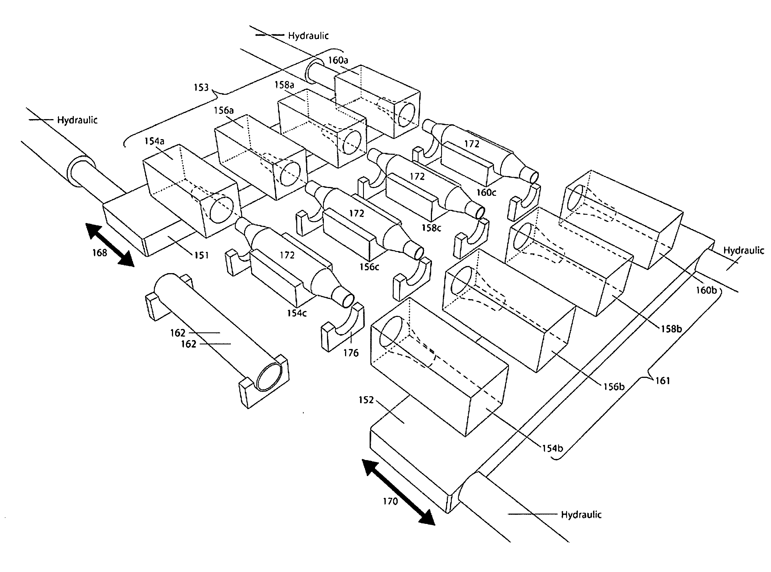
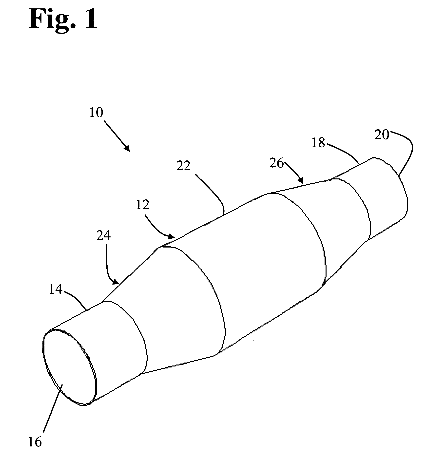
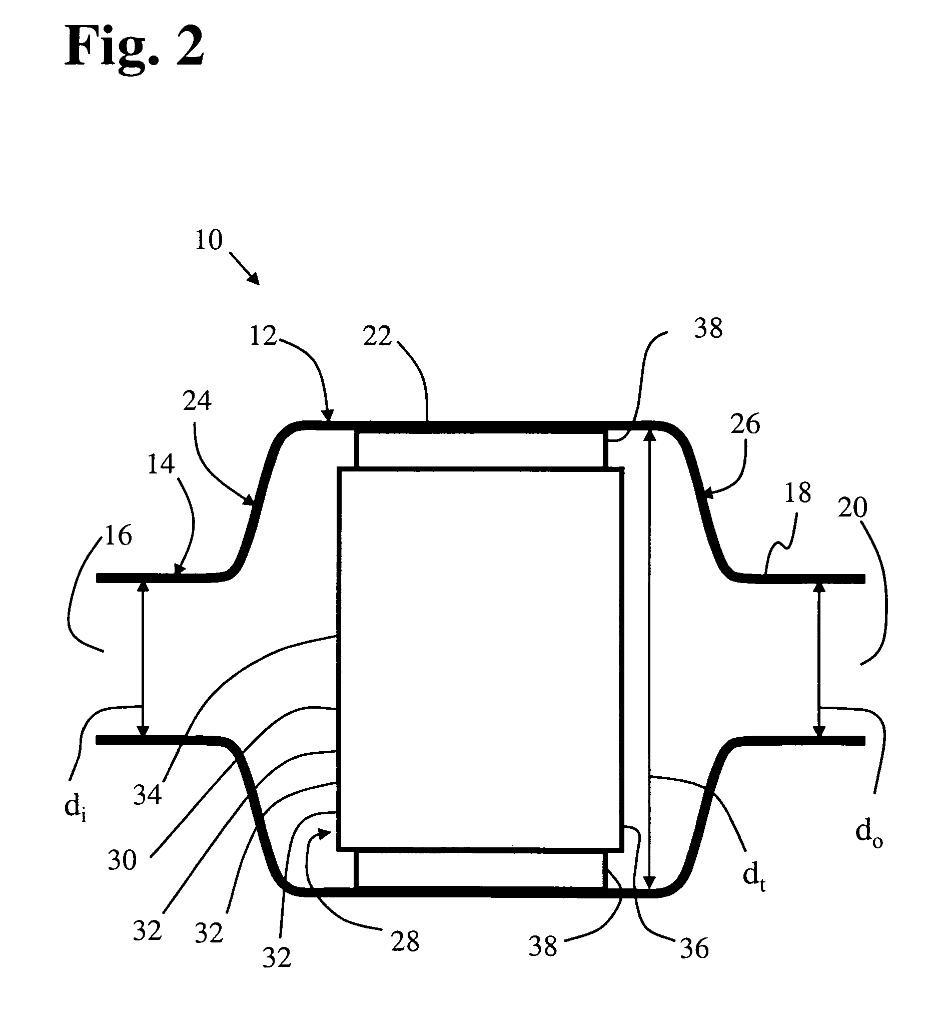
[0091]A catalytic converter of a type commonly used for emissions reduction from an automobile engine was formed using a catalytic element comprising a conventional platinum-group noble metal type of catalyst supported on the walls of multiple passages extending through a cordierite ceramic honeycomb structure. The honeycomb structure was about 3.6 inches in diameter and 3 inches long. The housing for the converter was formed from a seamless tube of 409 stainless steel alloy having an outside diameter of about four inches and 0.049-inch walls. The honeycomb structure was wrapped with an intumescent mat compressed to about 0.12 inches thickness, and the combined mat and ceramic were then inserted into the center part of the generally tubular converter housing. The ends of the housing were then end-formed to provide an inlet port section and an outlet port section, each of which having a diameter of two inches and a length of two inches....


PUM

PropertyMeasurementUnit
diametersaaaaaaaaaa
diametersaaaaaaaaaa
total lengthaaaaaaaaaa

Abstract

A catalytic converter for an internal combustion engine exhaust system comprises a single-piece, seamless metal housing having tubulated gas inlet and outlet ports and a tubulated intermediate section with at least one catalytic element therein. The converter is manufactured by a multi-step swaging process carried out in a transfer press. The press has a plurality of swaging stations that include swaging die sets that provide a graduated series of swaging steps. The process is operated continuously, with one of the swaging steps being carried out in each station during each press stroke.

Description

[0001]This application is a continuation-in-part of co-pending U.S. patent application Ser. No. 10 / 867,925, filed Jun. 15, 2004, which is a continuation-in-part of U.S. patent application Ser. No. 10 / 389,868, filed Mar. 18, 2003 and issued Jan. 30, 2007 as U.S. Pat. No. 7,169,365, and further claims the benefit of provisional U.S. Patent Application Ser. No. 60 / 367,419, filed Mar. 26, 2002. Each of application Ser. Nos. 10 / 867,925, 10 / 389,868 and 60 / 367,419 is incorporated herein in its entirety by reference thereto.BACKGROUND OF THE INVENTION[0002]1. Field of the Invention[0003]This invention relates to the field of automotive exhaust components; and more particularly, to a muffler, catalytic converter or the like, that is formed and housed within a seamless enclosure.[0004]2. Description of the Prior Art[0005]It is widely recognized that the exhaust emissions of internal combustion engines constitute a major source of air pollution throughout the world. The combustion process in t...

Claims


Application Information

Patent Timeline
Patent Type & Authority Applications(United States)
IPC IPC(8): B21D51/16
CPCB01D53/9454B01D2255/102B21D41/04B21D51/16Y10T29/49345F01N3/2853F01N3/2857F01N2450/02Y02T10/22B23P2700/03Y02T10/12
Inventor TURSKY, JOHN M.
Owner EVOLUTION IND INC
Why Eureka
Try Eureka