In modern microprocessors, increases in latencies have been an increasingly severe problem.
Thus, in terms of processor cycles to access a location in memory, latency has increased significantly.
That is, as
CMOS scaling is applied ever more aggressively, wire speeds do not scale at the same rate as logic speeds, leading to a variety of latency increases, e.g., increasing the time required to complete operations by requiring longer time to write hack their results.
However, the number of registers specified in architectures has not increased since the introduction of RISC computing (when the size of register files was increased from the then customary 8 or 16 registers to 32 registers) until recently.
However, to
exploit these larger register files, complex (and area intensive) renaming logic and out-of-order issue capabilities are required.
Even then, the inability to express the best schedule for the program using a
compiler or a skillfully tuned Basic
Linear Algebra Subprogram (BLAS) or other such
library limits the overall performance potential.
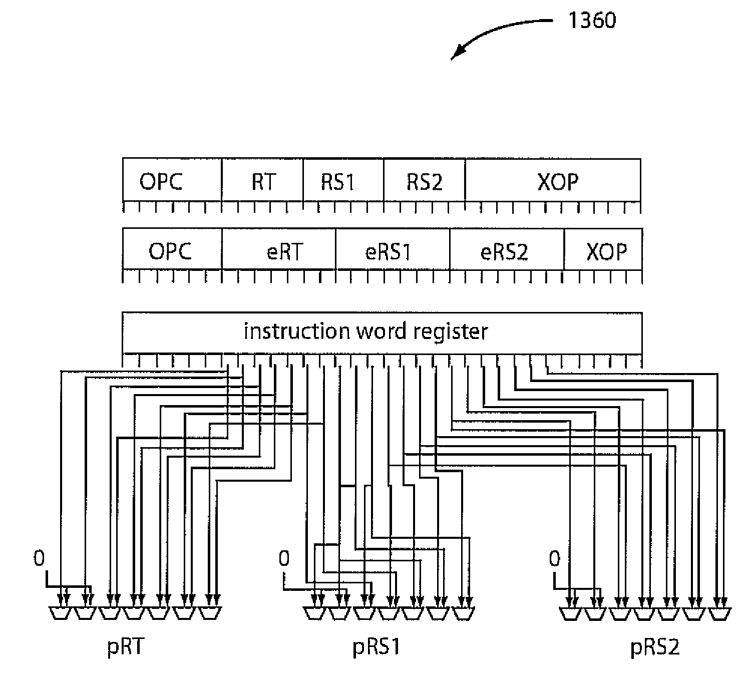
While this resolves the issue of instruction encoding space, it leads to inefficient encoding due to a reduction of
code density because an instruction word disadvantageously occupies more than a single
machine word, thereby reducing the number of instructions which can be stored in a given memory unit.
Legacy architectures, on the other hand, are not without deficiency.
For example, since many bit combinations have been assigned a meaning in legacy architectures, and certain bit fields have been
set aside to signify specific architectural information (such as extended opcodes, register fields, and so forth) legacy architectures offer significant obstacles to encoding new information.
Specifically, when allocating new instructions, the specification for these new instructions cannot arbitrarily allocate new fields without complicating the decoding of both the pre-existing and these new instructions.
Additionally, the number of bits in instruction sets with fixed instruction word width limits the number of different instructions that can be encoded.
This encoding limitation is causing increasing problems as instruction sets are extended.
However, it is difficult or impossible to specify additional registers in the standard 32-bit RISC instruction encoding.
Among the problems associated with
variable length CISC encoding is the additional complexity it requires in the instruction decode, resulting in additional decode pipeline stages in the
machine or a reduced frequency.
Moreover, another problem with
variable length CISC encoding is that it allows instructions to span natural memory boundaries (e.g., cache line and page boundaries), complicating instruction fetch and virtual address translation.
Another problem with
variable length CISC encoding is that such a CISC approach cannot be compatibly retrofitted to a RISC architecture.
Further, no mechanisms are defined to address the issue of page-spanning instructions, and so forth.
However, if all instructions are 64-bits, approximately twice as much memory space as is currently used would be required to hold instructions (which would disadvantageously affect elements like an instruction cache).
In addition, this is incompatible with existing RISC code with 32-bit instructions.
This provides a simplification of some aspects, e.g., an implementation can avoid the issues associated with bundles crossing natural memory boundaries, but does not address the other significant drawbacks.
However, it “wastes” bits specifying the interaction between instructions.
The three instruction packing also forces additional complexity in the implementation to deal with three instructions at once.
Finally, this three instruction packing format has no requirement to be compatible with existing 32-bit instruction sets, and there is no obvious mechanism to achieve compatibility with (legacy) 32-bit RISC encodings.
Those skilled in the art will understand that the cost of decoding a prefix, determining the mode and the
bank field, accompanied by fetching the instruction being modified by the prefix, incurs a significant complexity,
delay and hardware inefficiency.
In particular, the decoding of the prefix and
bank selector has to be performed early, leading to additional complexity.
In addition, prefixes are generally not readily employed in an architecture supporting only a fixed instruction word width.
Using the segment selector as a
bank selector for all operands of a given instruction is undesirable because it requires access to a
control register to identify a bank, and restricts all instructions to have operands coming from just a single bank, leading to inefficient
register allocation.
Thus, if a common value has to be combined with other operands residing in multiple banks, copies of the common value have to be maintained, computed and updated in all banks, such that they can be combined with the other operands residing in the other banks, leading to inefficient register usage due to data duplication, and inefficient performance profile due to the duplication of work to compute the common value in all banks.
This is undesirable because it requires the access to a
control register to identify a bank, and restricts all operations to have operands coming from just a single bank, leading to inefficient
register allocation.
Thus, if a common value has to be combined with other operands residing in multiple banks, copies of the common value have to be maintained, computed and updated in all banks, such that they can be combined with the other operands residing in the other banks, leading to inefficient register usage due to data duplication, and inefficient performance profile due to the duplication of work to compute the common value in all banks.
Specifically, the disadvantages relate to the fact that register names can only be properly resolved after the address generation phase, as a multitude of
memory address forms can refer to a memory mapped register.
This will increase the latency of access to these registers to almost the latency for first level
cache access.
This limitation is particularly severe for RISC processors, which can only
reference memory operands in load and store operations, imposing the additional cost of performing copies from the memory-mapped in-core registers to computationally useable
operand registers.
In another disadvantageous aspect of the '646 Patent, when addresses are generated before address generation from a subset of “preferred forms”, address
aliasing can occur and lead to incorrect program execution.
In yet another disadvantageous aspect of the '646 patent, when an address to such in-core register is added to a
linked list, and accessed by a remote processor, this will lead to
data coherence inconsistencies.
Alternatively, costly methods for accessing such registers from SMP remote nodes have to be implemented and provided.
While this extends the number of registers implemented in the processor, such an approach is not suitable for the extension of the register set useable by a
single process or program.
This is limited in that only the architected set of prior art registers can be accessed at any one time, thus not making more than the number of prior art registers available at any one time.
In another disadvantageous aspect of the '625 patent, additional instructions are required in the
instruction stream to update the control word.
While this extends the number of registers implemented in the processor, this is not suitable for the extension of the register set useable by a
single process or program.
In general,
microcode has different requirements, and methods from
microcode are recognized to not be applicable to architected instruction sets by those skilled in the art due to issues related to the internal representation, requirements for compatibility, decoding of instructions and detection of data and structural hazards (which are not supported in the restricted
microcode programming model), as well as the need of maintaining compatible across generations of a design.
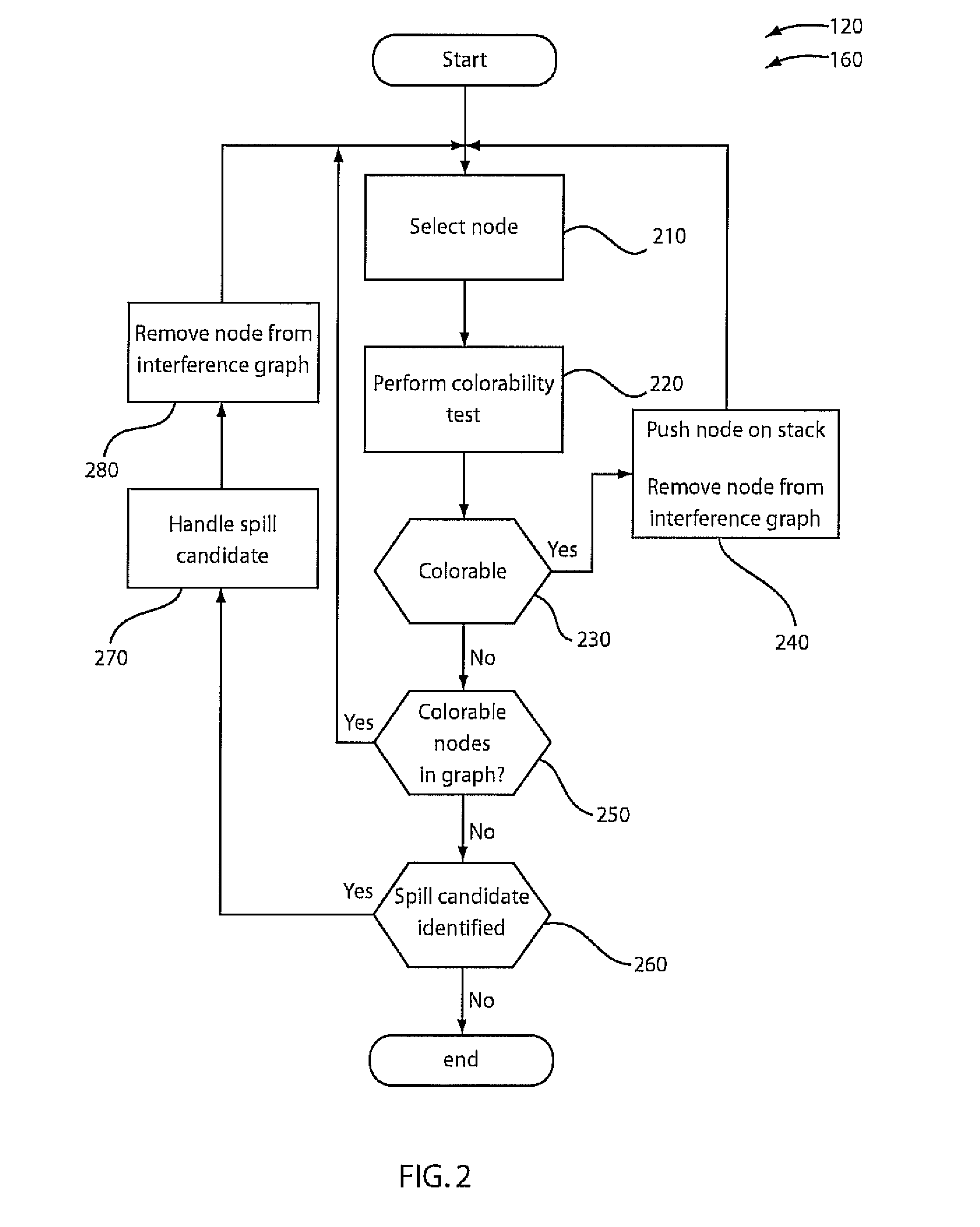
However, while this test allows the representation of constraints in an irregular architecture, it is only an approximation of colorability.
In addition, while this test allows for the representation of colorability for a wide range or architectures, the test is expensive to implement, resulting in slow compilation times.
Disadvantageously, this test cannot determine colorability in an extended register specification as set forth herein.
Disadvantageously, these tests are only an approximation and are excessively general, and hence expensive to implement.

