Indirect Optical Free-Space Communications System and Method for the Broadband Transmission of Hight-Speed Data

a technology of optical free space and broadband transmission, applied in the field of indirect optical free space communications system for broadband transmission of highspeed data, can solve the problems of high cost of equipment with a great many cables and plug connections, affecting the quality of analog signal transmission, so as to reduce equipment complexity, facilitate overlap, and reduce the effect of equipment complexity

Inactive Publication Date: 2008-09-11
AIRBUS OPERATIONS GMBH
View PDF13 Cites 24 Cited by
  • Summary
  • Abstract
  • Description
  • Claims
  • Application Information

AI Technical Summary

Benefits of technology

[0027]Therefore one or more shading elements is also preferably provided, serving to shield the light reflected by the shared surface of one cell with respect to a receiver belonging to a different cell.
[0028]The light sources of neighboring cells especially advantageously have different wavelengths. In this way the surfaces reflecting signals and / or the surfaces in the field of vision of the receivers can easily overlap at the interfaces, for example. The different wavelengths of the light are 810 nm and 960 nm; these wavelengths are especially easy to separate by simple filters of the receiver. Therefore, corresponding light sources, preferably LEDs or lasers of the two wavelength ranges, are used at the transmission end.
[0029]The different measures are especially preferably combined, which yields special advantages.
[0030]Although the two aisles of an airplane, for example, are separated by the beam guidance as independent communication cells because of the shadowing that occurs in the borderline area due to the baggage receptacles in the middle area, slightly overlapping cells with different wavelengths are implemented along the aisles. The full reflection / adjustment of the field of vision is accomplished preferably in such a way that although overlapping may be possible (but need not be possible) in the borderline area of neighboring cells, there is no overlapping with the next-but-one cell. Therefore, only two different labelings L1 and L2 are needed along an aisle, alternating approximately in the arrangement L1-L2-L1-L2-L1-L2. This reduces the equipment complexity due to the wavelengths required to a number limited to two, especially since filtering need not be very sharp, but on the other hand, almost any data speed can be achieved due to the alternating use.

Problems solved by technology

First, cable must be installed to each terminal, i.e., each receiver / transmitter and / or each data station in the interior must be equipped with a suitable plug and the cable must be provided with a suitable plug connection at the location of the connection. The receiver / transmitter therefore has only limited flexible mobility and also needs a standardized plug connection, and the number of possible receivers is predetermined by the number of plugs on the cable or by the number of cables. The location of the data station is also limited by the predetermined spatial arrangement. This is problematical where the number and location of receivers is not predetermined and must be kept flexible. However, equipment with a great many cables and plug connections is expensive and susceptible to trouble.
Electric cables are also exposed to interference due to electromagnetic radiation (EMF).
There is a drastic loss of quality during transmission of analog signals in particular but interference also occurs in the case of digital transmission.
This problem is especially difficult to handle in transportation means because in a moving vehicle, unlike a fixed building, the environment and the incident radiation cannot be kept constant over the transmission link, so that incident radiation can at most be reduced by overdimensional shielding during travel.
However, such highly shielding cables are heavy, expensive and immobile.
Furthermore, the transportation means itself may cause a high level of electromagnetic contamination, i.e., EMF.
In addition, an electric cable is not only exposed to incident radiation but also emits radiation itself.
Furthermore, such a system is also susceptible to interception.
Another disadvantage is the limited data rate which can be transmitted due to the limited bandwidth of electric cables.
The higher the data rate, the more difficult is its transmission over an electric connection owing to damping and dispersion and the greater is the problem of EMF and shielding.
However, inflexibility with regard to the number and location of the stations to be connected in the interior remains a problem, especially since the optical fibers and plug connections cost more in general than the corresponding electric connections and are more difficult to install.
Furthermore, it is difficult to provide free plug connections for stations to be connected later and / or it can be done only at great expense.
However, a disadvantage here is that the data transmission rate is limited in principle, and there is still the problem of EMF radiation and emission of EMF into other systems of the transportation means as well as the problem of security against interception.
In the case of transportation means that are used mainly in various countries of the world, such as airplane or ships, the local regulations for the frequency bands and types of modulation that are used must be taken into account, which greatly restricts the choice of available frequency bands and complicates their international use.
However, the disadvantage of this method is that there must be a direct line-of-sight connection between the transmitter and receiver, and the distance between the two must be relatively small, typically <1-2 meters.
This is possible only in the optical range used here because such a sharp delineation would not be possible with radio waves because of the non-directional propagation at lower frequencies.
For example this also takes into account the fact that the data rates are limited to approximately 100 Mbit / s due to multipath propagation.

Method used


Image

  • Indirect Optical Free-Space Communications System and Method for the Broadband Transmission of Hight-Speed Data
  • Indirect Optical Free-Space Communications System and Method for the Broadband Transmission of Hight-Speed Data
  • Indirect Optical Free-Space Communications System and Method for the Broadband Transmission of Hight-Speed Data

Examples


Embodiment Construction

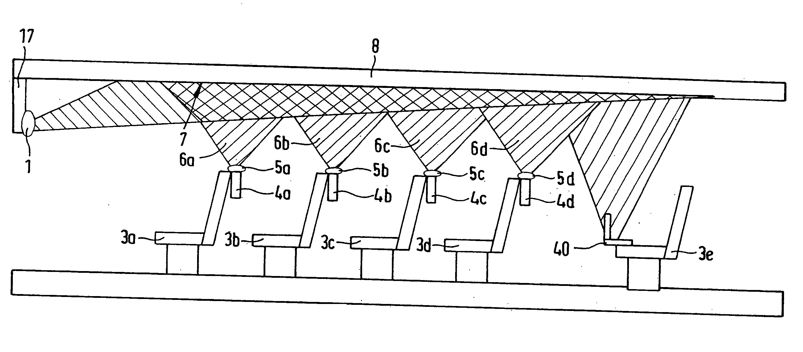
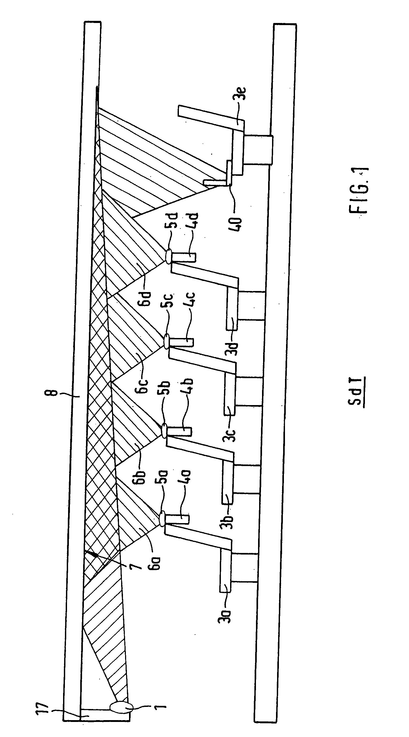
[0050]FIG. 1 shows a schematic sectional view of a known optical free space communication system that is improved upon by the present invention and that is described in detail in German Patent DE 101 07 538 B4.

[0051]A “distributor” or transmitter 1 which is mounted on the transportation means, e.g., on a holder 17, is arranged in such a way that the light emitted by it strikes a surface 7 at a distance on a ceiling 8 of a transportation means. The transportation means is, for example, an airplane, a motor vehicle, a motor vehicle, a train, bus, streetcar, satellite or the like. Data stations 5a, 5b, 5c, 5d, 40 and the respective multimedia stations 4a, 4b, 4c, 4d are arranged at a distance from the distributor 1 and receive the light reflected and / or scattered by the surface 7. Thus the light goes by an indirect route from the distributor 1 to the data stations; an oblique hatched region illustrates the light emitted by the distributor and a region 6a, 6b, 6c, 6d having oblique hatc...


PUM


Abstract

An indirect optical free-space communications system provides broadband transmission of high-speed data in in transportation vehicles such as aircraft. The system includes a transmitter with a light source that can be modulated and a receiver with a photo detector, adapted to receive light that is emitted from the transmitter and to convert it into an electric signal. The transmitter and the receiver are directed onto at least one common surface, which reflects the light emitted from the transmitter before it reaches the receiver. The free space communications system is cellular and includes several cells, each of which has a transmitter and at least one corresponding receiver. The cells are configured in such a way that crosstalk with a respective adjoining cell is prevented. The cells are thus independent of one another.

Description

BACKGROUND AND SUMMARY OF THE INVENTION[0001]This invention relates to an indirect optical free-space communications system for broadband transmission of high-speed data and a method for broadband transmission of high-speed data.[0002]Communication between computers or other technical systems is important not only in office rooms or computer rooms but increasingly also in the interior of transportation means because data communication is also increasingly important there. For example, larger transportation means, such as buses, trains, airplanes, ships, etc. are equipped with displays, earphone connections, input terminals and / or receivers or data stations, so the passenger can be entertained or informed during the trip and service personnel can exchange data with central data stations, etc. In such applications, very large volumes of data are usually transmitted by a central data memory and / or transmitter to one or more data receivers or vice-versa.[0003]The data transmission, whic...

Claims


Application Information

Patent Timeline
Patent Type & Authority Applications(United States)
IPC IPC(8): H04B10/00H04B10/114
CPCH04B10/1149
Inventor SCHMITT, NIKOLAUS-PETER
Owner AIRBUS OPERATIONS GMBH
Why Eureka
Try Eureka