Method and apparatus for extending equipment uptime in ion implantation

a technology of ion implantation and equipment, which is applied in the field of in situ cleaning system, can solve the problems of increasing affecting the precise qualities of the ion beam, and forming particles that are deleterious to the device yield, and reducing the effective reaction rate. , the effect of reducing the pressure in the chamber to be cleaned

Inactive Publication Date: 2008-09-18
SEMEQUIP
View PDF100 Cites 56 Cited by
  • Summary
  • Abstract
  • Description
  • Claims
  • Application Information

AI Technical Summary

Benefits of technology

[0021]Briefly the present invention relates to a cleaning system, for example, an in situ cleaning system for use with semiconductor processing equipment. In accordance with an important aspect of the invention, the cleaning system provides for dynamic cleaning of the semiconductor processing system by varying the pressure of the cleaning gas over time during a cleaning cycle. In one embodiment of the invention, the cleaning gas is applied to the semiconductor processing system in repeated pressure cycles. Each pressure cycle begins with the pressure of the cleaning gas at PMIN. The pressure of the cleaning gas is increased to a maximum pressure PMAX during a fill portion of the pressure cycle and maintained for a dwell time selected to allow the available reactants to generate the desired end products. The pressure in the chamber to be cleaned is then reduced during a vent portion of the pressure cycle to permit venting of the reaction products. As such, each time the chamber to be filled is vented and re-filled, reaction products are removed and new reactants are introduced into the chamber to be cleaned, effectively increasing the effective reaction rate.

Problems solved by technology

The precise qualities of the ion beam, or of the plasma forming chamber in the case of PLAD or PIII, can be severely affected by condensation and deposit of the feed material or of its decomposition products on surfaces of the ion beam-producing system, and in particular surfaces that affect ionization, ion extraction and acceleration.
Also, if the deposits are loosely adhered to those surfaces, there is a risk that particles will be formed which are deleterious to device yield if they propagate to the surface of the substrate.
Otherwise a condition known as “cross-contamination” exists and is undesirable.
A serious contamination effect occurs when feed materials accumulate within the ion source so that they interfere with the successful operation of the source.
Such a condition invariably has called for removal of the ion source and the extraction electrode for cleaning or replacement, resulting in an extended “down” time of the entire ion implantation system, and consequent loss of productivity.
With other feed materials, however, detrimental deposits have formed in hot ion sources.
Cold ion sources suffer more from the deposition of feed materials than do hot sources.
The use of these gases and vapors in cold ion sources has resulted in significant materials deposition and has required the ion source to be removed and cleaned, sometimes frequently.
These ion sources suffer from cross-contamination (between N- and P-type dopants) and also from particle formation due to the presence of deposits.
When transported to the substrate, particles negatively impact yield.
Cross-contamination effects have historically forced FPD manufacturers to use dedicated ion implanters, one for N-type ions, and one for P-type ions, which has severely affected cost of ownership.
Boron hydrides, such as decaborane and octadecaborane, present a severe deposition problem when used to produce ion beams, due to their propensity for readily dissociating within the ion source.
Eventually, depending on the design of the ion source, the buildup of condensed material interferes with the operation of the source and necessitates removal and cleaning of the ion source.
Contamination of the extraction electrode has also been a problem when using these materials.
Such instabilities affect the precision quality of the ion beam and can contribute to the creation of contaminating particles.
US 2005 / 0260354 A1, entitled “In-Situ Process Chamber Preparation Methods for Plasma Ion Implantation Systems” (“the '354 publication”), one known problem with such cleaning systems for use with semiconductor processing equipment is the efficacy of such systems.
However, the effect of running the cleaning gas with the source gas on the ion beam characteristics is problematic.
One problem is the dilution of the desired dopant in the ion beam, reducing implanted dose rate on the wafer and wafer throughput.
A second problem is that the cleaning is not a well-controlled process for removing specific deposits, and may etch away beam line components which do not require deposit removal.

Method used


Image

  • Method and apparatus for extending equipment uptime in ion implantation
  • Method and apparatus for extending equipment uptime in ion implantation
  • Method and apparatus for extending equipment uptime in ion implantation

Examples


Embodiment Construction

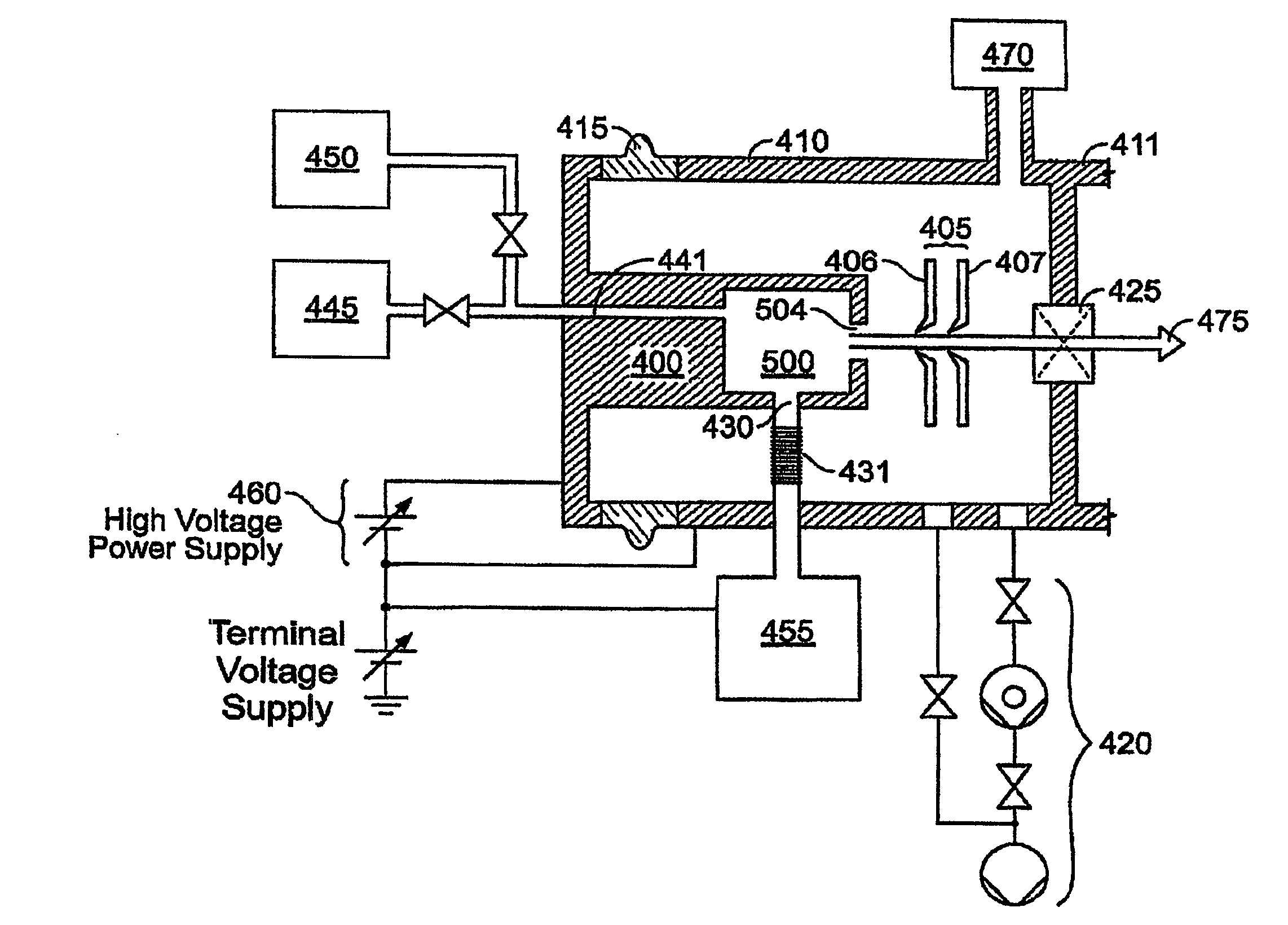
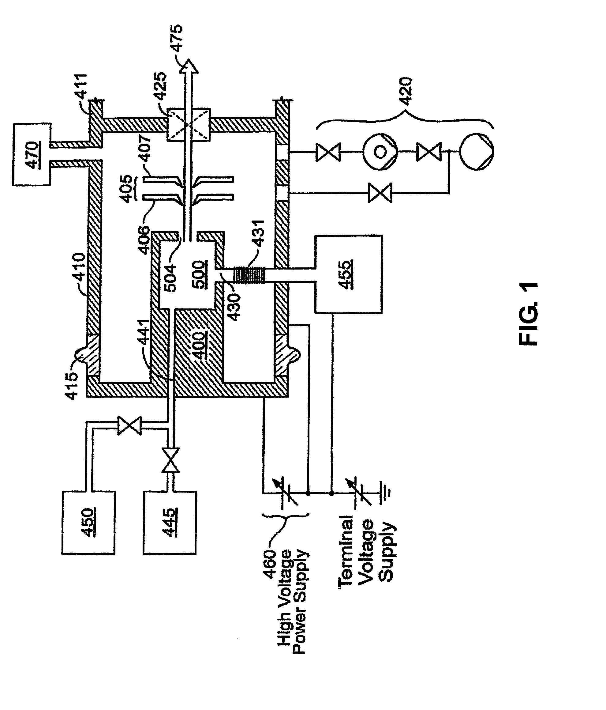
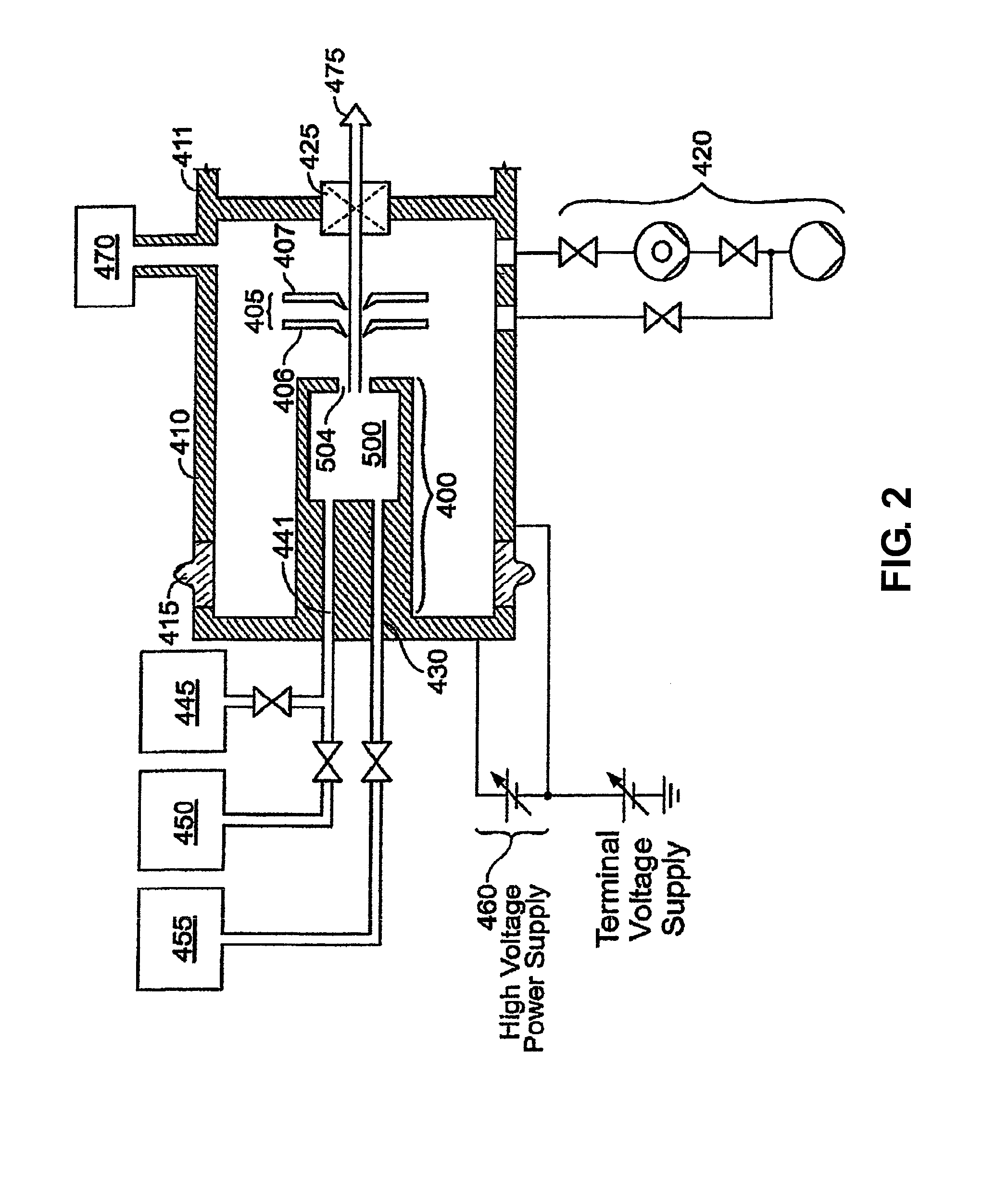
[0049]The present invention relates to a cleaning system, for example, an in situ cleaning system for use with semiconductor processing equipment. In accordance with an important aspect of the invention, the cleaning system provides for dynamic cleaning of the semiconductor processing system by varying the pressure of the cleaning gas over time to create pressure gradients during a cleaning cycle. In particular, in a preferred embodiment the pressure of the cleaning gas is increased to a maximum pressure PMAX to fill the chamber to be cleaned with the cleaning gas. The maximum pressure PMAX is maintained for a dwell time selected to allow the available reactants to generate the desired end products. The pressure in the chamber to be cleaned is then reduced to create pressure gradients to cause the cleaning gas to reach areas which did not get sufficient gas or were not impinged by the cleaning gas and to permit venting of the reaction products. As such, each time the chamber to be f...


PUM

PropertyMeasurementUnit
vapor pressureaaaaaaaaaa
voltageaaaaaaaaaa
surface areaaaaaaaaaaa

Abstract

An in situ cleaning system is disclosed for use with semiconductor processing equipment. In accordance with an important aspect of the invention, the cleaning system provides for dynamic cleaning of the semiconductor processing system by varying the pressure of the cleaning gas over time during a cleaning cycle. In particular, the cleaning gas is applied to the semiconductor processing system in repeated pressure cycles. Each pressure cycle begins with the pressure of the cleaning gas at PMIN. The pressure of the cleaning gas is increased to a maximum pressure PMAX during a fill portion of the pressure cycle and maintained for a dwell time selected to allow the available reactants to generate the desired end products. The pressure in the chamber to be cleaned is then reduced during a vent portion of the pressure cycle to permit venting of the reaction products. As such, each time the chamber to be filled is vented and re-filled, reaction products are removed and new reactants are introduced into the chamber to be cleaned, increasing the effective reaction rate.

Description

CROSS REFERENCE TO RELATED APPLICATIONS[0001]This application is a continuation-in-part of commonly owned co-pending U.S. patent application Ser. No. 10 / 582,392, filed on Dec. 9, 2004, entitled “Method and Apparatus for Extending Equipment Uptime in Ion Implantation”, which is a nationalization under 35 USC § 371 of PCT Application No. PCT / US04 / 41525, filed on Dec. 9, 2004, which claims priority to and the benefit of U.S. Provisional Application No. 60 / 529,343, filed on Dec. 12, 2003. all hereby incorporated by reference.BACKGROUND OF THE INVENTION[0002]1. Field of the Invention[0003]The present invention relates to in situ cleaning system for use with semiconductor processing equipment and more particularly to an in situ cleaning system with improved cleaning efficacy in which the pressure of the cleaning gas within the semiconductor processing system to be cleaned is dynamically varied.[0004]2.0 Description of the Prior Art[0005]Ion beams are produced from ions extracted from an i...

Claims


Application Information

Patent Timeline
Patent Type & Authority Applications(United States)
IPC IPC(8): B08B5/00B08B13/00
CPCB08B7/00B08B7/0035C23C14/48C23C14/564H01J37/08H01J2237/31705H01J37/3171H01J2237/006H01J2237/022H01J2237/0827H01J37/304
Inventor HORSKY, THOMAS N.MANNING, DENNISCOOK, KEVIN S.
Owner SEMEQUIP
Why Eureka
Try Eureka