Method of Designing and Manufacturing Artificial Joint Stem with Use of Composite Material

a composite material and joint stem technology, applied in the field of designing and manufacturing the artificial joint stem with the use of composite materials, can solve the problems of unreacted monomer resin components which are not polymerized, harmful effects on the human body, and affecting the life of youth with a long life expectancy, so as to prevent mistakes, reduce costs, and be made in a short period of time

Inactive Publication Date: 2008-09-25
B I TEC
View PDF11 Cites 198 Cited by
  • Summary
  • Abstract
  • Description
  • Claims
  • Application Information

AI Technical Summary

Benefits of technology

[0086]According to this invention, the laminating position is displayed on the forming die of the stem as irradiating the laser beam thereon, which enables to prevent from causing mistakes in the determination of the laminating position and laminating order and to manufacture the stem as meeting the design conditions such as the desirable stiffness.
[0087]As mentioned above, according to the invention, one can provide the method of designing and manufacturing the artificial joint stem with the use of composite material that may be made in a short period of time with a lower cost, which connects bones without using cement, not getting loose for a long period of time, excellent in the durability, and is provided with the stiffness and the external form appropriate for each patient.

Problems solved by technology

However, the cement-type uses two kinds of resin, base resin and hardener as the cement 109, and if they are not mixed enough, or the mixture ratio is inaccurate, unreacted monomer resin components which are not polymerized would remain and have harmful effects on the human body through the melt-out, and it is a source of causing various damages to the human body.
Therefore, there is hesitation in using the cement-type to the youth with a long life expectancy.
Then, when the bone is cracked, patients suffer from the pain over a long period of time since there is no way to treat it so far.
As for the total hip prosthesis, the cement-type requires re-operation at a rate of five to twenty percent within ten years, but it is difficult to pull the stem 105 with the cement-type out of bone, and the re-operation itself is not easy.
However, the cement-less type fixes the stem 105 as bone grows, narrowing the gap between the bone and the stem 105, and it takes several months until the bone fills the gap, and the stem 105 is firmly fixed, and then patients need a rehabilitation period, which prolonged a period of patients' hospitalization, imposing a burden on patients.
Moreover, due to a long period of hospitalization it was difficult to adopt the method to elderly people who were concerned with negative effects on other functions such as motor function.
Also, the conventional stem 105 is made of metal such as cobalt alloy and titanium alloy, and because these alloys are difficult to cut, it is very hard to process the convex portion 116 with microscopic convexo-concave on the surface of the stem 105, which made the stem 105 very expensive.
Moreover, these alloys are excellent in corrosion resistance, and because it is difficult to apply adhesive surface treatment to the surface to form electrically neutral and stable oxide coating for adhesion of hydroxyapatite's crystal, the bonding strength of the hydroxyapatite is not stable and the hydroxyapatite exfoliates, which, as a result, creates a problem that the stem 105 gets loose.
Therefore, it is necessary to smooth the surface by undercutting the sculpheight by hand after the machine work, but the stem 105 such as titanium alloy is difficult to cut, and the finishing requires very hard work.
Therefore, the cement-less type stem made of titanium alloy became very expensive.
Moreover, when convexo-concave is formed on the stem 105 to fit the internal form of the medullary canal 117, the finishing work would becomes difficult, it is too costly to adopt, and as the production time of stem 105 becomes longer the time a patient spends in the hospital becomes longer, which means the burden on patients cannot be relieved.
However, as shown in FIG. 22, the fit and fill is low in the proximal side and the contacting area is small, and thus there are areas where force from the stem 105k is applied to bone and other areas where the force is not applied, which results in stress shielding.
As a result, rotation and fixation of the stem 105k was not satisfactory.
There has been a case reported in which a corrosion pit caused metal fatigue and fractured the stem.
However, none of the above inventions have been in practical use in the current status.
That is to say, the above inventions to make the center of the stem metallic and its external side wrapped around with FRP have ended in failure since the stem becomes loose in the early postoperative period, resulting from micro motion between the FRP and bone or between the FRP and the center of the metallic section.
The cause of this failure is thought to be the fact that the stem's bending stiffness only applies to the center of the metallic section, making the overall bending stiffness low, and the distribution of stress in the area contacting bone is concentrated at both ends, leading to the occurrence of micro motion since the stem cannot resist the stress.
While avoiding harmful substance melt out, it does not solve any other problems.
With this method it is difficult to attain the external form that fits the internal form of the medullary canal, necessitating the coating layer further outside of the second-direction strength support, and the stem may get loose since the stress is concentrated in both ends of the coating layer.
Moreover, in Published Japanese Translations of PCT International Publication No. 7-501475, carbon fiber reinforced plastic having carbon fibers embedded in the thermoplastic polymer is used as a stem, and stiffness of the stem is changed as varying the wrap angle of that carbon fiber from area-to-area of the stem; however, also this stem, because the external form is formed by wrapping carbon fiber, a concave form cannot be formed in the circumferential direction (fiber direction of the carbon fiber) of the stem, and it is difficult to attain the external form that fits the internal form of the medullary canal and initial fixation of a stem that raises the fit and fill cannot be achieved.
However, the conventional system is manufactured from materials that are difficult to cut such as titanium alloy, and it was impossible to process in the hollow section, and thus the method in FIG. 24(D) cannot be applied to the conventional metallic stem.

Method used


Image

  • Method of Designing and Manufacturing Artificial Joint Stem with Use of Composite Material
  • Method of Designing and Manufacturing Artificial Joint Stem with Use of Composite Material
  • Method of Designing and Manufacturing Artificial Joint Stem with Use of Composite Material

Examples


Embodiment Construction

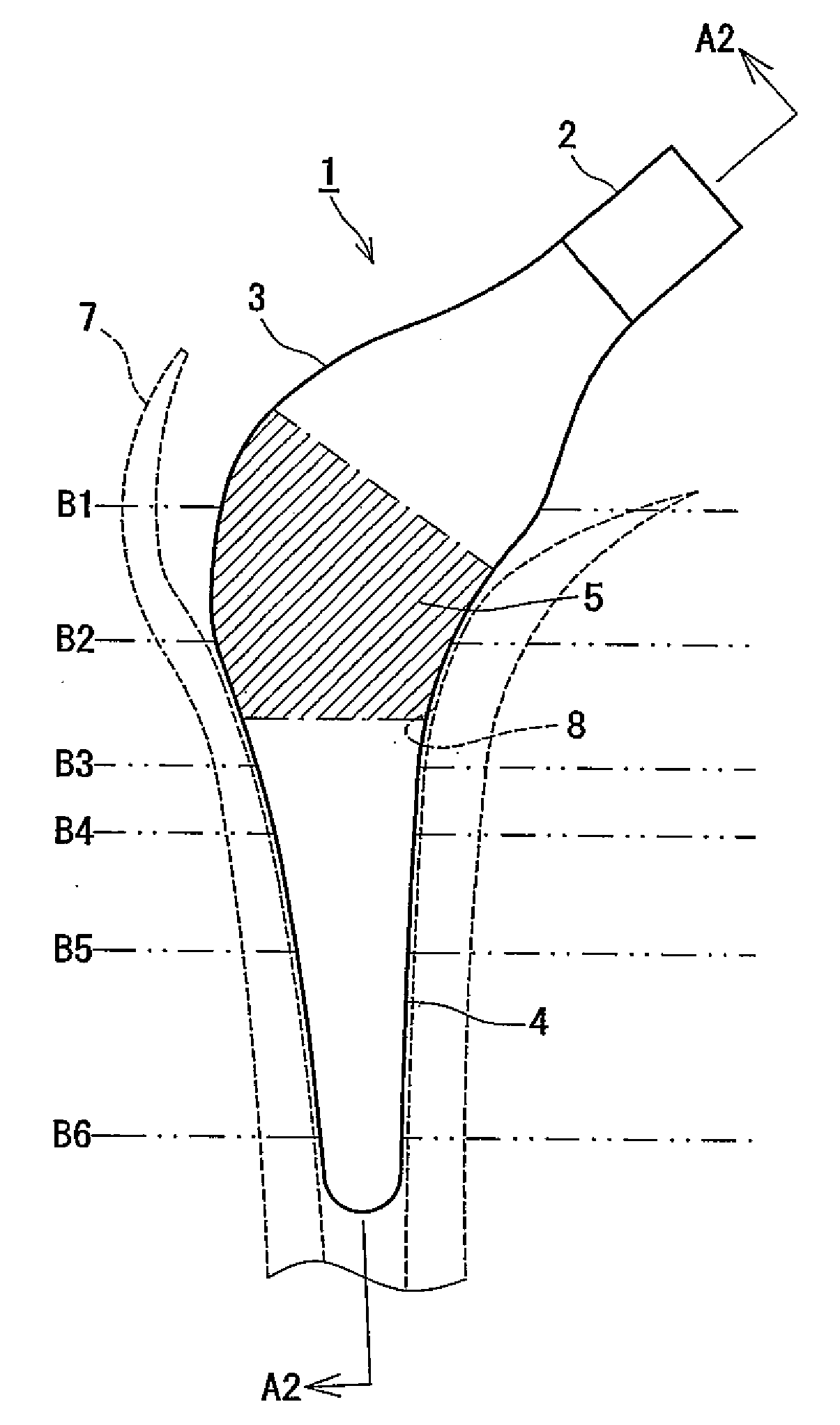
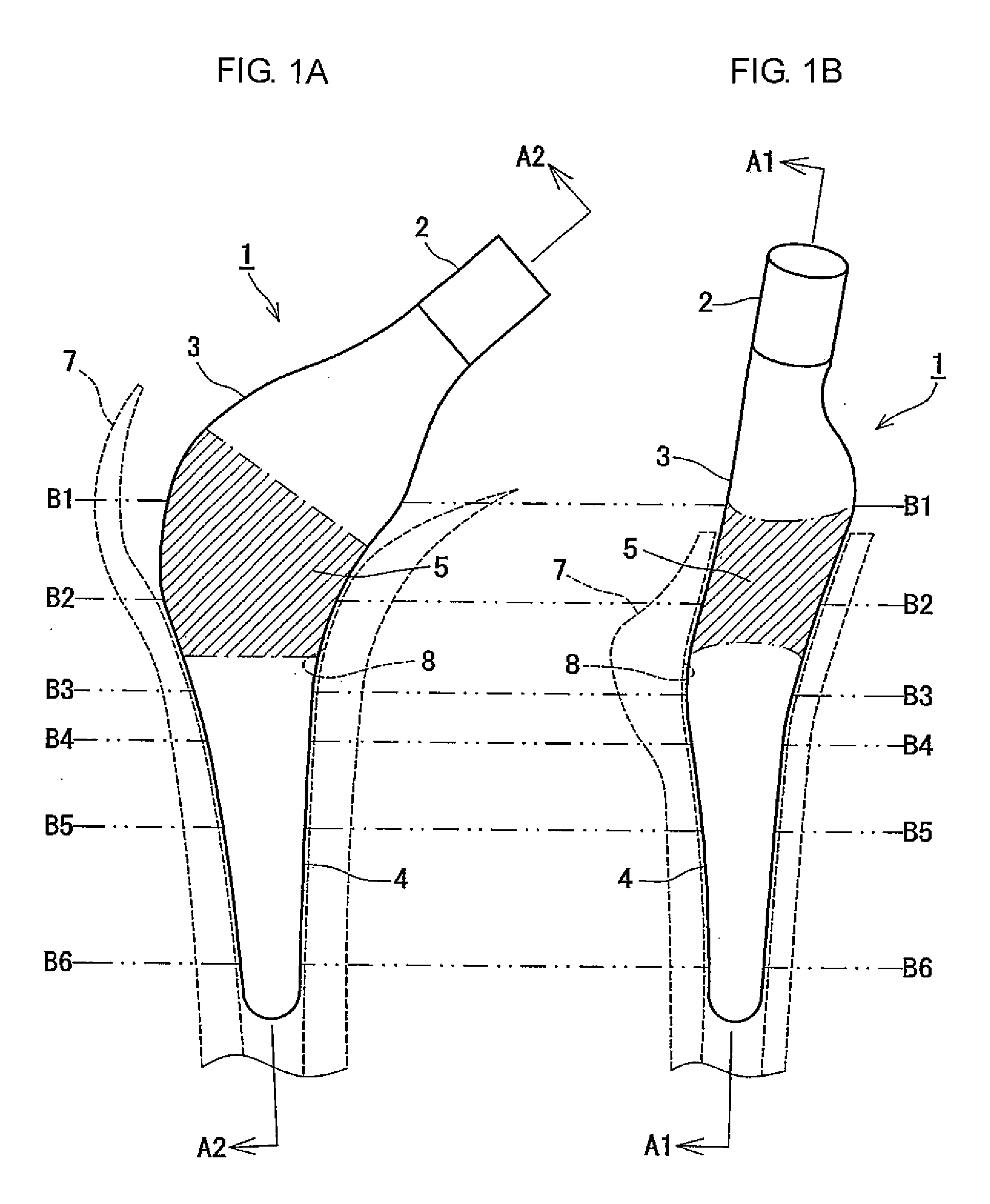
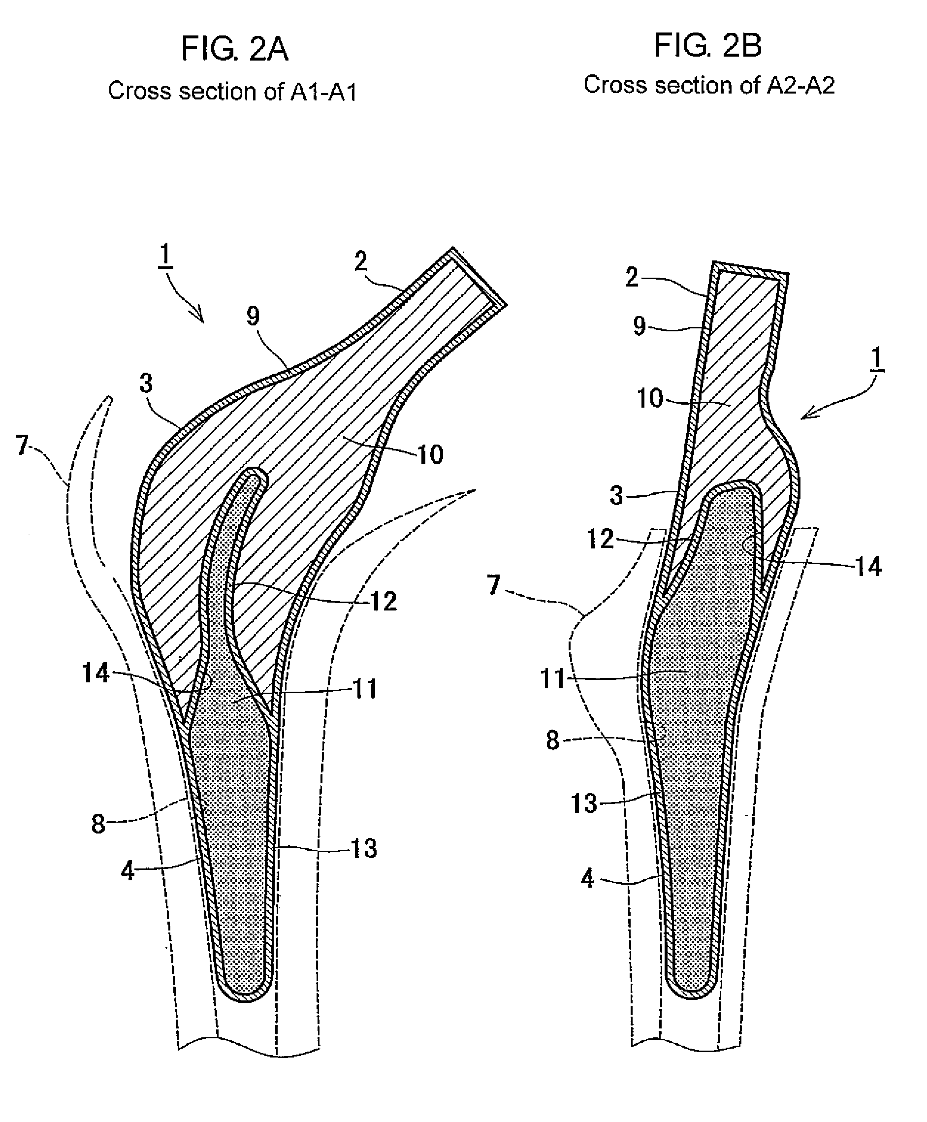
[0114]Below, the preferred embodiments are illustrated in details based on the FIGS. 1-9. FIG. 1A is a front view of the artificial joint stem manufactured with the use of the method of designing and manufacturing the artificial joint stem using the composite material in the invention, and FIG. 1B is its side view thereof. FIG. 2A is the section view taken along the line A1-A1 of FIG. 1, and FIG. 2B is the section view taken along the line A2-A2 of FIG. 1. FIG. 3 is a set of cross section views of B1-B6 in FIG. 1 at the respective height that is cut in each level perpendicular to the axes. FIG. 4A is a cross section view showing the enlarged structure of the surface treatment section, and FIG. 4B is a cross section view of the further enlarged B part shown with an arrow in FIG. 4A. FIG. 5 is a block view of the functional structure of the computer in the method of designing and manufacturing the artificial joint stem using the composite material of this invention. FIG. 6 is a flow c...


PUM


Abstract

The method of designing and manufacturing the artificial joint stem, comprising steps of performing analysis of the internal stress of the artificial joint stem and bone and the adhesive stress of the artificial stem and bone, using the computer, based on the three dimension data indicating the structure of the bone formed by using plural tomographic images of the bone, the design condition involving the form and stiffness of the artificial joint stem configured by using at least one of the tomographic images and the three dimension data, wherein if the result of the analysis does not satisfy the design condition, the condition is changed to have the computer reanalyze and if the result of the analysis satisfies the design condition, the artificial joint stem is designed and manufactured with the stem data based on the result of analysis and the design condition.

Description

FIELD OF THE INVENTION[0001]This invention relates to a method of designing and manufacturing an artificial joint stem as being implanted in a bone to form an artificial joint, particularly to the method of designing and manufacturing the artificial joint stem with the use of composite materials.BACKGROUND OF THE INVENTION[0002]It has long been known that an artificial joint made to imitate a joint is implanted when a damaged joint is removed due to a broken bone. As one example of this artificial joint, FIG. 13 shows a structure of a conventional total hip prosthesis used for a hip prosthesis. This total hip prosthesis 100 is comprised of a socket 102 fixed to a pelvis 101, a spherical head 104 equivalent to a femoral head of a femur 103 and a stem 105 embedded in the femur 103.[0003]As shown in the figure, the socket 102 and the head 104 make a pair and have a function of a spherical bearing. This socket 102 consists of synthetic resins such as high-density polyethylene, and the s...

Claims


Application Information

Patent Timeline
Patent Type & Authority Applications(United States)
IPC IPC(8): A61F2/36A61F2/30A61F2/00A61F2/32A61F2/34
CPCA61F2/30965A61F2/30942A61F2/34A61F2/36A61F2/3662A61F2/367A61F2/3676A61F2002/30004A61F2002/30112A61F2002/30113A61F2002/30125A61F2002/30136A61F2002/30158A61F2002/30322A61F2002/30616A61F2002/30828A61F2002/30892A61F2002/30929A61F2002/30948A61F2002/30952A61F2002/30957A61F2002/3611A61F2002/3631A61F2002/3664A61F2230/0004A61F2230/0006A61F2230/0008A61F2230/0026A61F2250/0014A61F2250/0026A61F2/30767A61F2/30771A61F2/32A61F2002/30878
Inventor BANDOH, SHUNICHIZAKO, MASARU
Owner B I TEC
Why Eureka
Try Eureka