
Portable autonomous material processing system

a technology of material processing and portable devices, which is applied in the field of portable plasma arc torch systems for processing materials, can solve the problems of inconvenient portability of plasma arc cutting systems, large gas consumption, and inability to efficiently adapt plasma arc torch systems to facilitate portability, so as to reduce the size and cost of the torch, and increase the system size and cost of production

Active Publication Date: 2008-10-02
HYPERTHERM INC
View PDF67 Cites 30 Cited by
  • Summary
  • Abstract
  • Description
  • Claims
  • Application Information

AI Technical Summary

Benefits of technology

[0022]Contact starting is one known technique for generating the pilot arc in a plasma torch. Contact starting is advantageous because it does not require high frequency equipment and does not normally generate electromagnetic interference. Typical contact starting systems include pilot arc circuits having a means for supplying pilot arc current, a pilot arc resistor, a current sensor, and a pilot arc relay, or a combination thereof, for transferring current from a pilot arc mode to a transferred arc mode. These pilot arc circuits increase the system size and cost of production.
[0023]A contact start plasma arc torch is provided that includes a passive pilot arc circuit that decreases the size and cost of the torch. The plasma arc torch includes a torch body, an electrode having a longitudinally disposed axis and mounted in the body, a nozzle having a longitudinally disposed axis, the nozzle axis being disposed substantially collinearly with the electrode axis, a power supply coupled to the electrode, the nozzle and a workpiece, the power supply providing a current for operating the torch in a pilot arc mode and a transferred arc mode, and a pilot arc circuit coupled between the power supply and the nozzle, the pilot arc circuit controlling the operation of the torch in the pilot arc mode. Either the electrode or the nozzle can be translatable.
[0029]Advantages of the contact start plasma arc torch include: a passive pilot arc starting circuit; automatically disconnecting the pilot arc circuit at a predetermined time; easily setting the magnitude of the pilot arc current; eliminating the need for current sensing and logic control of the pilot arc circuit; seamlessly transferring current from the pilot art circuit to the workpiece; and minimization of the components resulting in decreased production costs of the plasma torch.
[0032]A voltage supplied by the battery to the plasma arc torch assembly can be about at least about 45 volts of DC power. In some embodiments, the battery provides sufficient voltage to a torch electrode without requiring power conditioning circuitry that includes voltage step-up circuitry or high frequency switching.
[0040]The invention, in another aspect, features a method for minimizing gas consumption of a portable plasma arc torch. The method can include commencing a flow of gas to the portable plasma arc torch from a portable, finite supply of gas, initiating a plasma arc, terminating the plasma arc and sacrificing electrode life to minimize gas consumption by eliminating or substantially reducing a flow of the gas about an electrode of the plasma arc torch during preflow or postflow conditions, to less than approximately 10 seconds before commencement or after termination of the plasma arc, thereby minimizing gas consumption.

Problems solved by technology

Traditionally, plasma arc cutting systems are not portable because they require a large, cumbersome gas source (or a continuous, fixed gas source) and large amounts of power drawn from the electrical power grid via a corded attachment.
Despite cordless power tools being pervasive in the commercial market, plasma arc torch systems have yet to be efficiently adapted for easy, portable usage.
One design difficulty is caused by the relatively large gas consumption of a plasma arc torch.
Another design difficulty is caused by the high power requirements of the plasma arc torch system, e.g., about 1.32 kW output for a low power system such as the Powermax™ 190C manufactured by Hypertherm, Inc. of Hanover, N.H.; 8.4 kW output for a medium power torch system such as the Powermax 1000 manufactured by Hypertherm and up to 16,000 kW output for a high power torch system such as the Powermax 1650 manufactured by Hypertherm.
There exists a difficult balance between the performance of the torch, the lifetime of the gas and power sources, and actual physical size of the plasma arc torch system.

Method used


Image

  • Portable autonomous material processing system
  • Portable autonomous material processing system
  • Portable autonomous material processing system

Examples


Embodiment Construction

[0078]Plasma arc torches have a wide variety of applications such as the cutting of thick plates of metal and the cutting of comparatively thin sheets of galvanized metal commonly used in heating, ventilating and air conditioning (HVAC) systems. The basic components of a plasma arc torch include a torch body, an electrode (cathode) mounted within the body, a nozzle (anode) with a central exit orifice, a gas source to provide a flow of an ionizable gas, electrical connections, passages for cooling and arc control fluids, and a power source that produces a pilot arc in the gas, typically between the electrode and the nozzle, and then a plasma arc, a conductive flow of the ionized gas from the electrode to a workpiece. The gas can be non-oxidizing, e.g. nitrogen, argon / hydrogen, or argon, or oxidizing, e.g. oxygen or air.

[0079]Various plasma arc torches of this general type are described in U.S. Pat. Nos. 4,791,268; 4,902,871; 5,170,033; 5,317,126; and 5,994,663, all commonly assigned ...


PUM

PropertyMeasurementUnit
voltageaaaaaaaaaa
timeaaaaaaaaaa
thickaaaaaaaaaa

Abstract

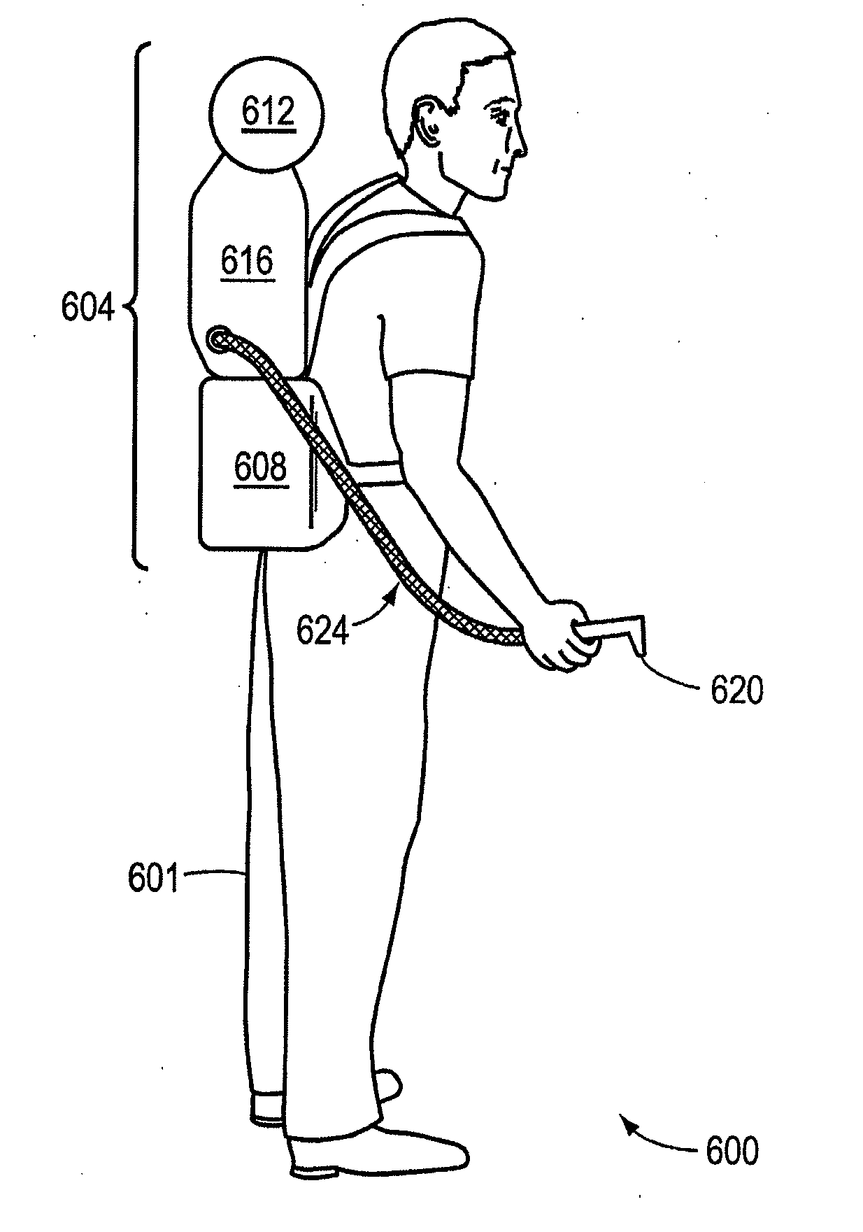
A portable plasma arc torch system can be used for processing materials. The system includes a replaceable or rechargeable power source and replaceable or rechargeable gas source. A controller communicates with at least one of the power source or the gas source. A plasma delivery device received via the controller current from the power source and gas from the gas source to generate a plasma arc at an output of the plasma delivery device. The plasma arc can be used to process materials such as metallic workpieces. The plasma arc torch can include a wearable portable assembly which includes the replaceable or rechargeable power and gas source. A plasma delivery device receives current from the power source in the assembly and gas from the gas source in the assembly to generate a plasma arc.

Description

RELATED APPLICATIONS[0001]This application is a continuation-in-part of U.S. Ser. No. 11 / 852,855 entitled “Wearable Autonomous Material Processing System” filed on Sep. 10, 2007 which is a continuation-in-part of U.S. Ser. No. 11 / 518,858 entitled “Autonomous Plasma Cutting System” filed on Sep. 11, 2006. This application is also a continuation-in-part of U.S. Ser. No. 11 / 518,856 entitled “Pilot Arc Circuit for a Contact Start Plasma Torch” filed on Sep. 11, 2006. This application also claims benefit of and priority to International Application No. PCT / US07 / 78044 entitled “Wearable Autonomous Material Processing System” filed on Sep. 10, 2007, which claims priority to and benefit of U.S. Ser. No. 11 / 518,858 entitled “Autonomous Plasma Cutting System” filed on Sep. 11, 2006. The contents of all of these applications are incorporated herein by reference in their entirety.TECHNICAL FIELD[0002]The invention relates generally to portable tools for processing materials. More specifically, ...

Claims


Application Information

Patent Timeline
Patent Type & Authority Applications(United States)
IPC IPC(8): B23K9/00B23K9/10
CPCB23K10/02H05H1/26H05H1/32B23K10/00H05H1/34H05H1/3423
Inventor SHIPULSKI, E. MICHAELSANDERS, NICHOLAS A.
Owner HYPERTHERM INC
Learn More