

Projection exposure apparatus
a technology of projection and exposure apparatus, which is applied in the direction of photomechanical treatment, instruments, printing, etc., can solve the problems of low efficiency of the exposure process, inability to correct chromatic aberration, and long exposure tim
- Summary
- Abstract
- Description
- Claims
- Application Information
AI Technical Summary
Benefits of technology
Problems solved by technology
Method used
Image

Examples
first embodiment
able Light-Shielding Body is Used
[0165]The substrate table 74 has a guide rail 31 for setting the light-shielding body. A first light-shielding body positioning portion 32 having a fan-shaped first light-shielding body 30 moves above the rim of the substrate CB. As a result, a blind zone 39 to which no patterns are transferred is formed on the rim of the substrate.
[0166]While the light is irradiated to the first light-shielding body 30, the body 30 is being heated. When the first light-shielding body 30 is heated, it may be deformed to thereby blind not only blind zone 39 but also another region of the exposure area EA. In consideration of this, it is preferable that the first light-shielding body 30 is made of heatproof-coated titanium alloy, invar alloy of Fe-36Ni having a low thermal expansion coefficient, kovar alloy of Fe29Ni-17Co, or ceramic.
[0167]When a negative type photo-resist is applied to the surface of the substrate, the non-irradiated portion (blind zone 39) of the res...
example 1
Retractable Light-Shielding Body
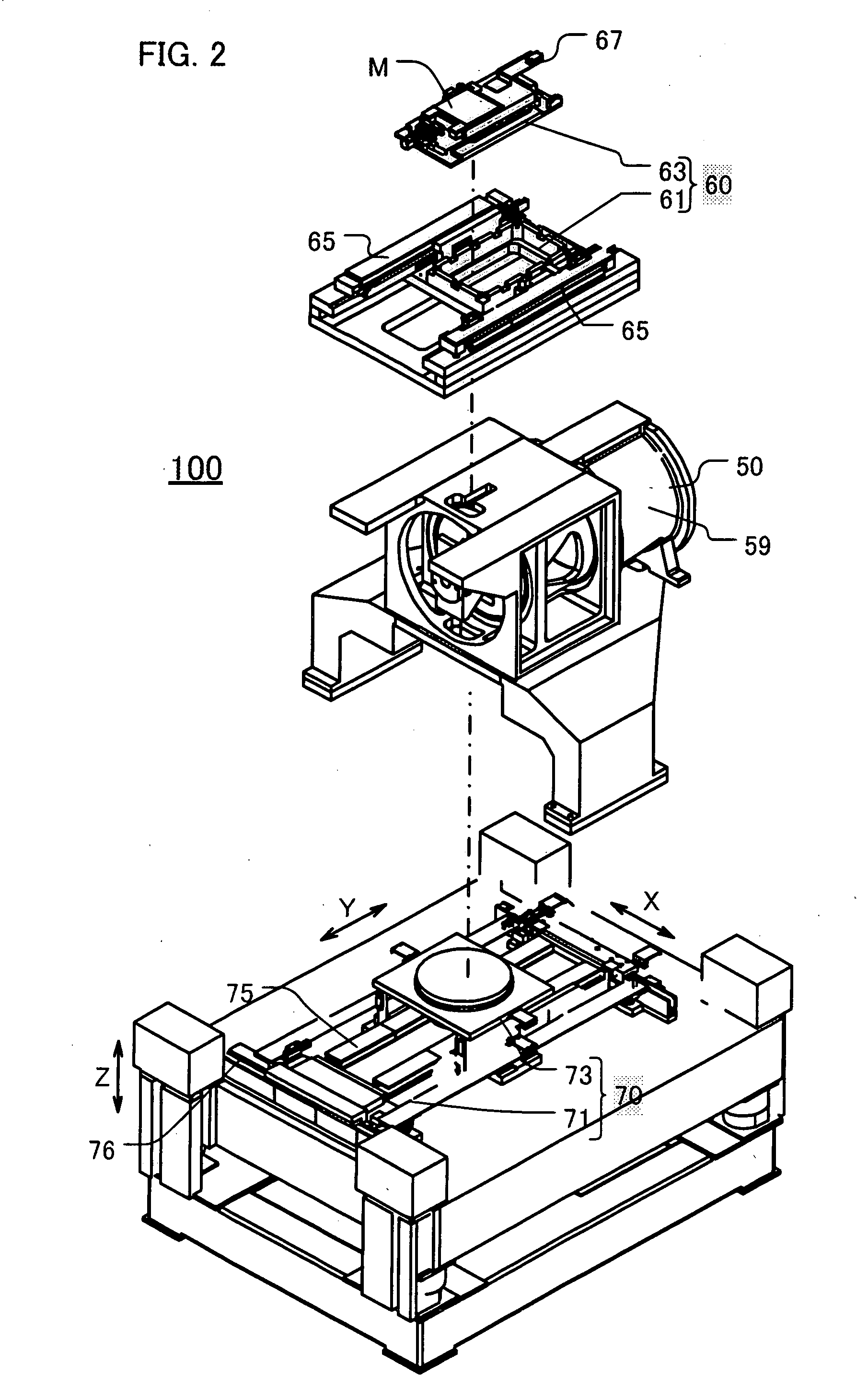
[0169]FIG. 17A shows the substrate table 74 of FIG. 2 as seen from the top.
[0170]Referring to this drawing, the substrate CB is held on the substrate table 74, and a ring-shape guide rail 31 is set around the rim of the substrate CB. The guide rail 31 is provided with the first light-shielding body positioning portion 32, and this portioning portion 32 can move around the rim of the substrate CB freely. In other words, the first light-shielding body positioning portion 32 can slide on the guide rail 31 at 360 degree. As the exposure location is approaching the rim of substrate CB, the position of the first light-shielding body 30 is determined based on the coordinate information of the substrate table 74. Therefore, the first light-shielding body 30 can be held at a predetermined location.
[0171]The substrate table 74 is equipped with moving mirrors 77 arranged on the X and Y sides, respectively. The combination of the moving mirrors and the laser int...
example 2
Laterally Movable Type Light-Shielding Body
[0194]In the example 1, the first light-shielding body 30 of the first light-shielding body positioning portion 32 rotates vertically, whereby the first light-shielding body 30 is moved between the blinding and escape locations. In contrast, in the example 2, the first light-shielding body 30 slides therebetween.
[0195]FIG. 20A shows a cross-section of a surrounding area of the first light-shielding body positioning portion 32-2 where the first light-shielding body 30 slides parallel to the X-Y plane. FIG. 20B shows the surrounding area of the first light-shielding body positioning portion 32-2 as seen from the top (on the Z axis).
[0196]The first light-shielding body 30 rotates around the rotational axis 34-2 by a rotary cylinder 33-2, thereby traveling between the escape location (plotted by dotted lines) and the blinding location (plotted by solid lines). As a result, the substrate CB is blinded appropriately. The width of a blind zone 39...
PUM
 Abstract
Description
Claims
Application Information