1. Special glue film: the special glue film is used to prevent the
thermoplastic packaging material from impregnating to the rear part of the
lead frame and thereby increasing the risk to insulation of the outer pins during encapsulation under
high pressure; however, the special glue film still can't completely prevent overflow of the
thermoplastic packaging material. If impregnation of the
thermoplastic packaging material still exists, the galvanized
coating on the pins may be damaged during post-treatment, and therefore degrades
soldering performance. As a result, the material cost, post-treatment cost, and quality will be affected to a certain degree.
2.
Palladium plating on both sides of the substrate: in order to ensure the wire
soldering process and the manufacture of outer pins can be completed in this process, expensive Pd material is coated on both sides of the
lead frame. Therefore, the
electroplating cost is high, and the
soldering parameters have to be specially set for the material; as a result, the smooth operation of the
production line will be affected due to inconsistency of parameters.
3.
Contamination: since specific chemical glue film is applied on the
lead frame, the solvents in the tape may be gasified under high temperature in different high temperature processes, and will contaminate or cover the pressing area of the chip and the soldering area of the pins, and thereby often causes unstable soldering.
4. Application flexibility of chip and outer pins: limited by the traditional lead frame, the chips and the outer pins have to be arranged in a fixed way; therefore, the application is not flexible.
5.
Soldering performance of the outer pins: limited by the traditional lead frame, the outer output pins are flush to the bottom of the molded body, and therefore are difficult to solder to the
printed circuit board. As a result, the soldering strength is low.
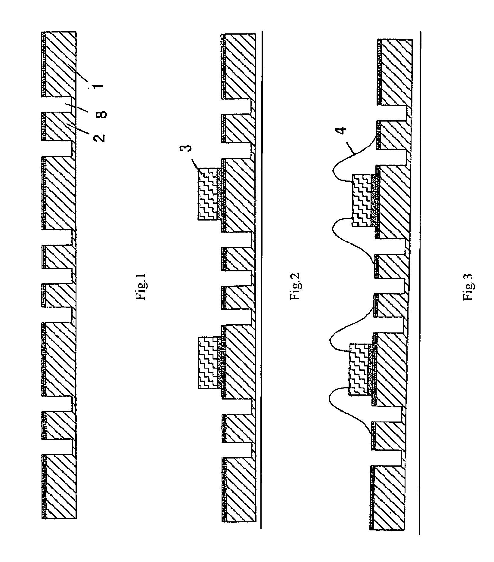
6.
Lead frame: since the lead frame is manufactured through penetrated
etching, the lead frame structure is mild. Therefore, the substrate can't be made of high-purity
copper material.
7.
Metal wire
ball bonding: since a penetrative
etching process is used, the back of the substrate has to be coated with glue film to prevent overflow. Since the glue film is soft, the positions of the soldering points may dislocate during wire soldering, which will cause loose contact of the soldering points and severely degrade reliability and production stability of the solder wires.
As a result, the thermoplastic encapsulation material will be loose, the water
absorption rate will increase, and the density will decrease, which will severely increase the production cost and decrease the qualified rate.
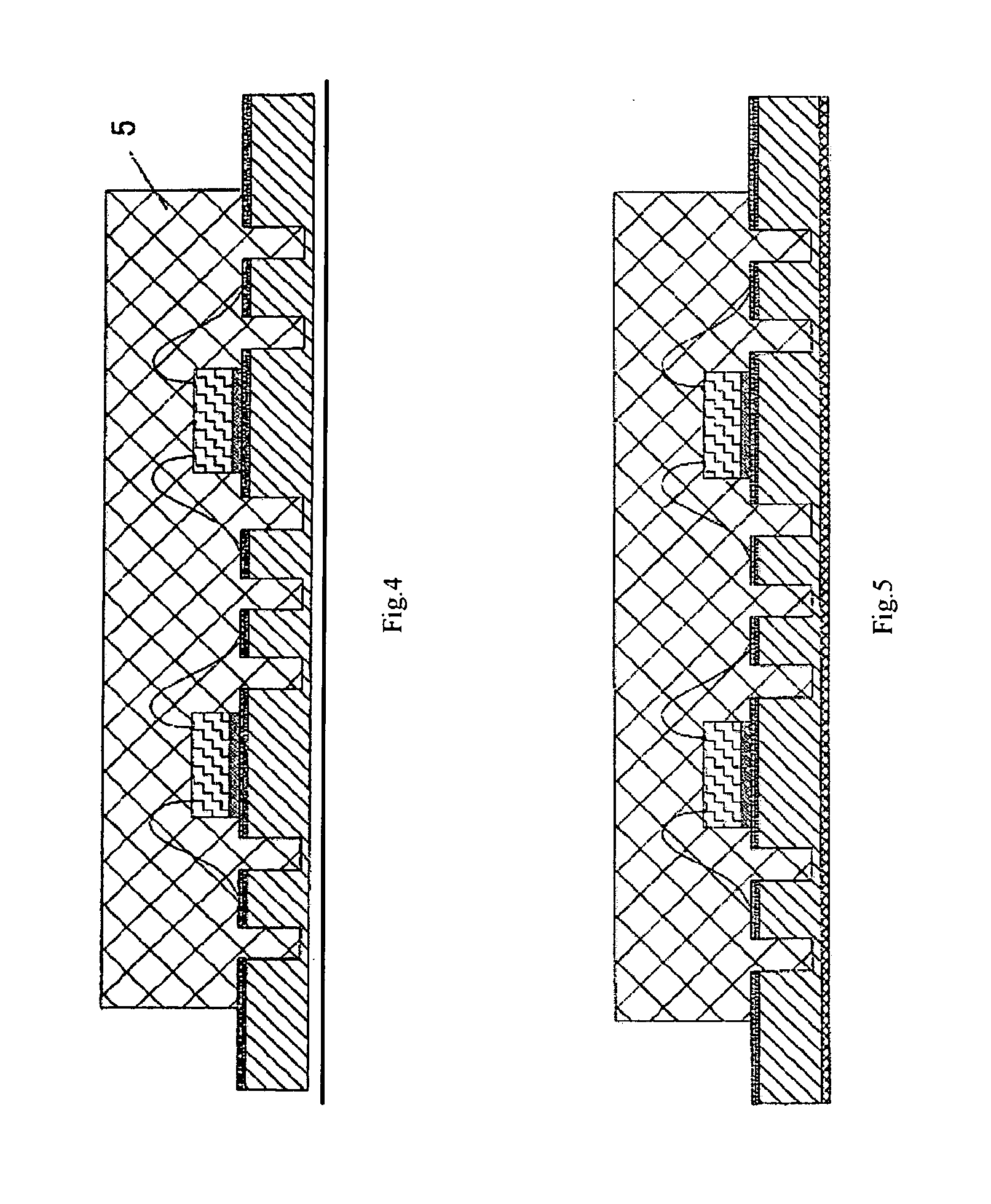
The output pin part of the product manufactured through leadless flat bond packaging is flush to the bottom of the molded body or even recessed, bad contact may occur due to the poor coplanarity of the pin surfaces in the
surface bonding process.
In addition, since the outer pins are recessed on the surface of the molded body, air may be trapped in the recess in the
surface bonding process, and therefore causes breaking of the contacts due to gas dilatation under high temperature.
Since the output pins are as flat as the bottom of the molded body or even recessed, the
tin paste on the pins may bond together and cause
short circuit under pressing in the
surface bonding process.
The inner pins are usually coated with
silver coating; however, the
silver coating doesn't bond well to the thermoplastic packaging material.
The outer pins that provide electrical output are usually made of Sn—Pd
alloy or pure Sn, which is easily oxidized and therefore affects
solderability.
Furthermore, the
shelf life of the product will be short.
Since the outer pins that provide electrical output are usually made of Sn—Pd
alloy or pure Sn and the Sn material has a
low melting point, the Sn material may be oxidized or even melted under the heat generated from friction with the
cutting tool in the
cutting process; therefore, the
solderability and the stability of electrical output of the outer pins will be severely degraded.

