Welding power source with automatic variable high frequency

a high frequency, automatic technology, applied in the field of welding systems, can solve the problems of poor quality welds, difficulty in striking and maintaining arcs, etc., and achieve the effect of reducing leakage, optimizing the high frequency energy level, and improving arc performan

Active Publication Date: 2008-10-30
ILLINOIS TOOL WORKS INC
View PDF34 Cites 28 Cited by
  • Summary
  • Abstract
  • Description
  • Claims
  • Application Information

AI Technical Summary

Benefits of technology

[0009]A welding system utilizing the power supply of the present invention has an advantage over the prior art in that such a system can adjust the high frequency output to deliver an optimal level of high frequency energy to a welding torch for a variety of welding applications. Another advantage of the present invention is that a variable high frequency output allows an operator to control the amount of EMI emitted from the welding system. A further advantage of the present invention is improved arc performance throughout the output range of the welder (i.e. lower intensity at low current welds, higher intensity at high current welds). A still further advantage is that an operator may adjust the high frequency output to reduce leakage and improve arc starting performance.
[0010]In accordance with embodiments of the present technique, the welding power supply includes a high frequency power source configured to provide a variable voltage output. The output of the high frequency power source is coupled to the primary winding of a transformer, establishing a resonant frequency signal with a capacitive storage device. The power supply further includes a switching device for regulating resonant rings between the capacitive storage device and the primary winding by charging and discharging the capacitive storage device at discrete time intervals. A high frequency controller regulates the output of the high frequency power source. As a result, the amount of high frequency energy in the resulting arc can be controlled and optimized for various welding applications.

Problems solved by technology

However, the arc itself may be somewhat difficult to strike and maintain based upon the welding power alone.
Although using a relatively constant voltage for initiating and maintaining arcs in TIG welding systems functions adequately, it is not without drawbacks.
Too much high frequency energy may cause excessive heat build up and result in a poor quality weld.

Method used


Image

  • Welding power source with automatic variable high frequency
  • Welding power source with automatic variable high frequency
  • Welding power source with automatic variable high frequency

Examples


Embodiment Construction

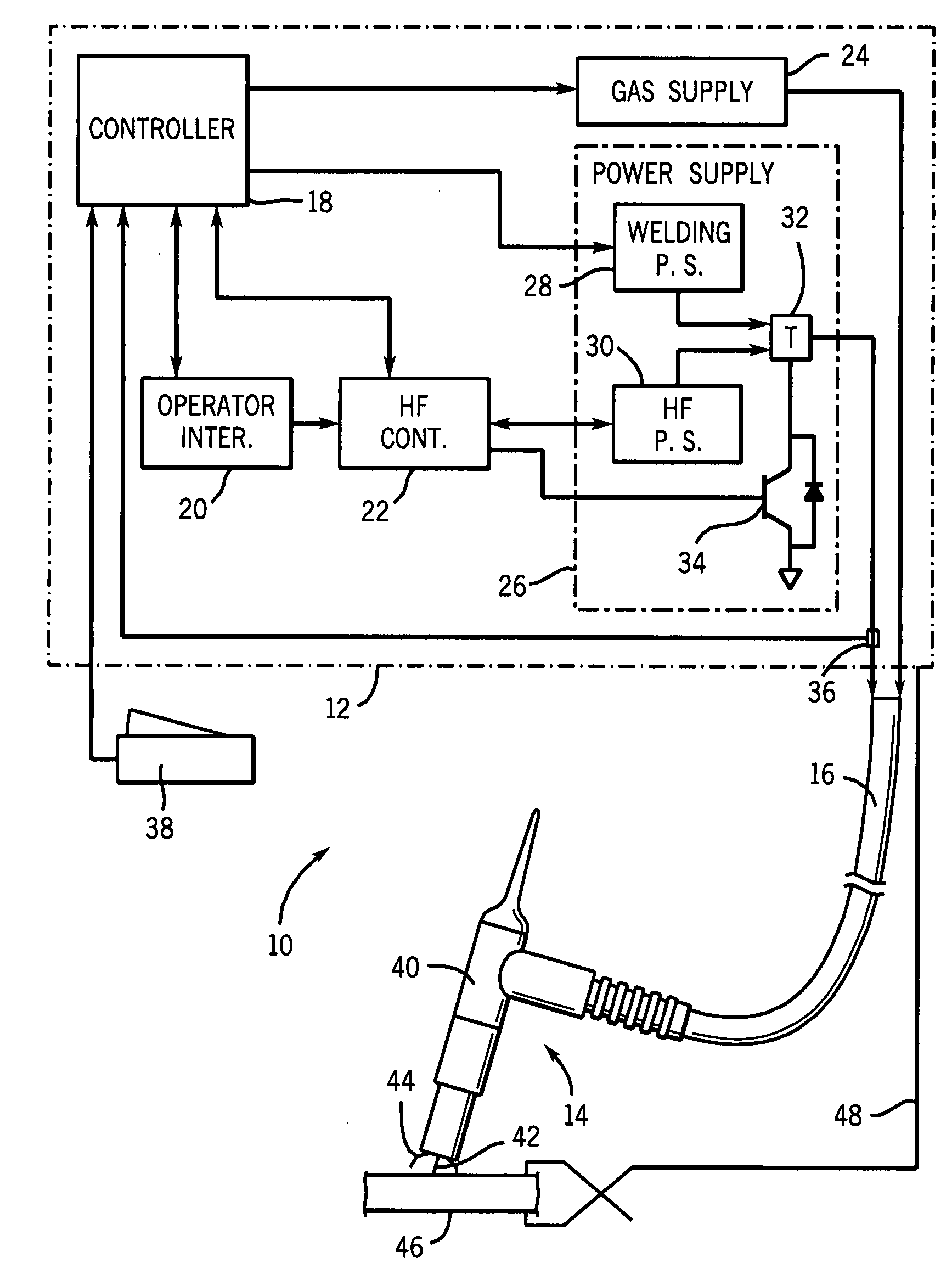
[0019]Turning now to the drawings, and referring first to FIG. 1, an exemplary welding system 10 is illustrated that makes use of a variable high frequency power source in accordance with the present invention. As noted above, it should be borne in mind that while this disclosure primarily discusses the application of this invention in TIG welding systems, different types of welding systems may be used and may benefit from the variable high frequency power source of the present invention.

[0020]The exemplary TIG welding system 10 of FIG. 1 includes a base unit 12 that supplies welding resources to a welding torch 14 via a welding cable 16. As illustrated, the base unit 12, which may typically be enclosed as a single unit in a stationary or portable cabinet, includes a welding system controller 18 that regulates operation of the various subsystems. The welding system controller 18 may include any suitable control circuitry and will typically be based upon a general purpose or applicat...


PUM

PropertyMeasurementUnit
frequencyaaaaaaaaaa
electrical poweraaaaaaaaaa
variable voltageaaaaaaaaaa

Abstract

A high frequency power source configured to provide a variable voltage output is described such as for use in welding systems. The high frequency power source charges a capacitive storage device. A transformer having a primary winding coupled to the output of the high frequency power source and establishing a resonant frequency signal with the capacitive storage device, and a secondary winding coupled to the welding power supply, superimposes the resonant frequency signals onto the welding power signal of the welding power supply during periods of the resonant rings. By varying the voltage output from the high frequency power source, the high frequency energy delivered to the welding torch can be optimized for a variety of welding applications.

Description

BACKGROUND[0001]The present invention relates generally to the field of welding systems, and more particularly to power sources used for creating high frequency, high voltage, low current pulses used to initiate and maintain arcs in such systems for the purpose of welding or cutting.[0002]A wide range of welding techniques have been proposed and are presently in use. In general, welding of metals is performed by melting one or more base metals in a work piece, as well as an adder metal in certain applications. One particularly useful welding technique, well suited for precise or intricate welding, is tungsten inert gas (TIG) welding. In TIG systems, a metal electrode, typically made of tungsten, is provided in a welding torch, and is generally not consumed (i.e., added to the base metal) during welding. Electric current is channeled through the electrode, and a flow of a shielding gas surrounds the electrode during the welding operation, generally provided by fluid conduits leading ...

Claims


Application Information

Patent Timeline
Patent Type & Authority Applications(United States)
IPC IPC(8): B23K9/10
CPCB23K9/0673
Inventor MANTHE, ALAN A.FERKEL, STEPHEN P.KOOSMANN, GLENN A.
Owner ILLINOIS TOOL WORKS INC
Why Eureka
Try Eureka