Method of Controlling the Oxygen Content of a Powder

a technology of oxygen content and powder, which is applied in the direction of metal-working apparatus, transportation and packaging, thin material processing, etc., can solve the problems of unintentional oxidation of the surface of powder during production, deterioration of mechanical properties of a component, and general low impact strength of dense bodies of powder metallurgy. , to achieve the effect of reducing the oxygen content of powder

Active Publication Date: 2008-10-30
SANDVIK INTELLECTUAL PROPERTY AB +2
View PDF13 Cites 1 Cited by
  • Summary
  • Abstract
  • Description
  • Claims
  • Application Information

AI Technical Summary

Benefits of technology

[0010]A method of reducing the oxygen content of a powder is provided. A canister is prepared with a getter, filled with the powder to be densified, evacuated and sealed. The canister is subjected to a hydrogen atmosphere at a temperature of 900-1200° C., which results in a diffusion of hydrogen into the canister through the walls thereof. The hydrogen forms moisture when reacted with the oxygen of the powder and the moisture in then reacted with the getter in order to remove oxygen from the powder to the getter. The atmosphere outside the canister is then altered to an inert atmosphere or vacuum, whereby hydrogen diffuses out of the canister.

Problems solved by technology

When producing powders, especially metallic powders, there is often an unintentional oxidation of the surfaces of the powders during production.
The oxides, especially the oxides of the powder surfaces, might lead to deteriorated mechanical properties of a component produced to near-net-shape (NNS) of a powder by densification.
However, dense bodies of SDSS produced by powder metallurgy generally suffer from low impact strength.
Another theory is that intermetallics and oxide precipitates both decrease the impact strength, however separately.
However, even other powder materials, such as metallic powders or hard materials, might have a too high content of oxygen to achieve good mechanical strength, such as impact strength, after compacted to a dense body.
However, merely utilising a getter material does not sufficiently reduce the oxygen content to the desired low levels of all powders, especially of all powders of steels.
This is especially difficult in powders wherein the carbon content is low, such as ≦0.1%.
The time for reduction, and hence the result, is difficult to accomplish in a controlled manner and in a cost-effective way.

Method used


Image

  • Method of Controlling the Oxygen Content of a Powder
  • Method of Controlling the Oxygen Content of a Powder

Examples


example 1

[0033]Two powders produced by nitrogen-gas atomisation were tested. The composition of the powders are listed in Table 1, all in weight percent except oxygen which is in parts per million.

TABLE 1OAlloyCrNiMoMnSiCuCNppm126.26.23.00.580.541.80.0390.3230216.912.92.41.060.60—0.0210.17155

[0034]2-mm mild steel canisters with a dimension of 92×26×150 mm were utilised. The interior of the 92×150 mm walls of the canisters were attached with 0.125 mm metal foils of Ti by spot-welding.

[0035]All canisters were filled with powder, evacuated and sealed according to standard procedure. Canisters with Ti-foil getter were treated according to the method described above. First, the heating was carried out rapidly up to 500° C., subsequently at a rate of 5° C. / min up to a, in advance, chosen reduction temperature with a holding time of 60 minutes. Thereafter, the temperature was set to 900° C. and the environment outside the canisters was changed from hydrogen to argon. After 1 hour, the furnace heati...

example 2

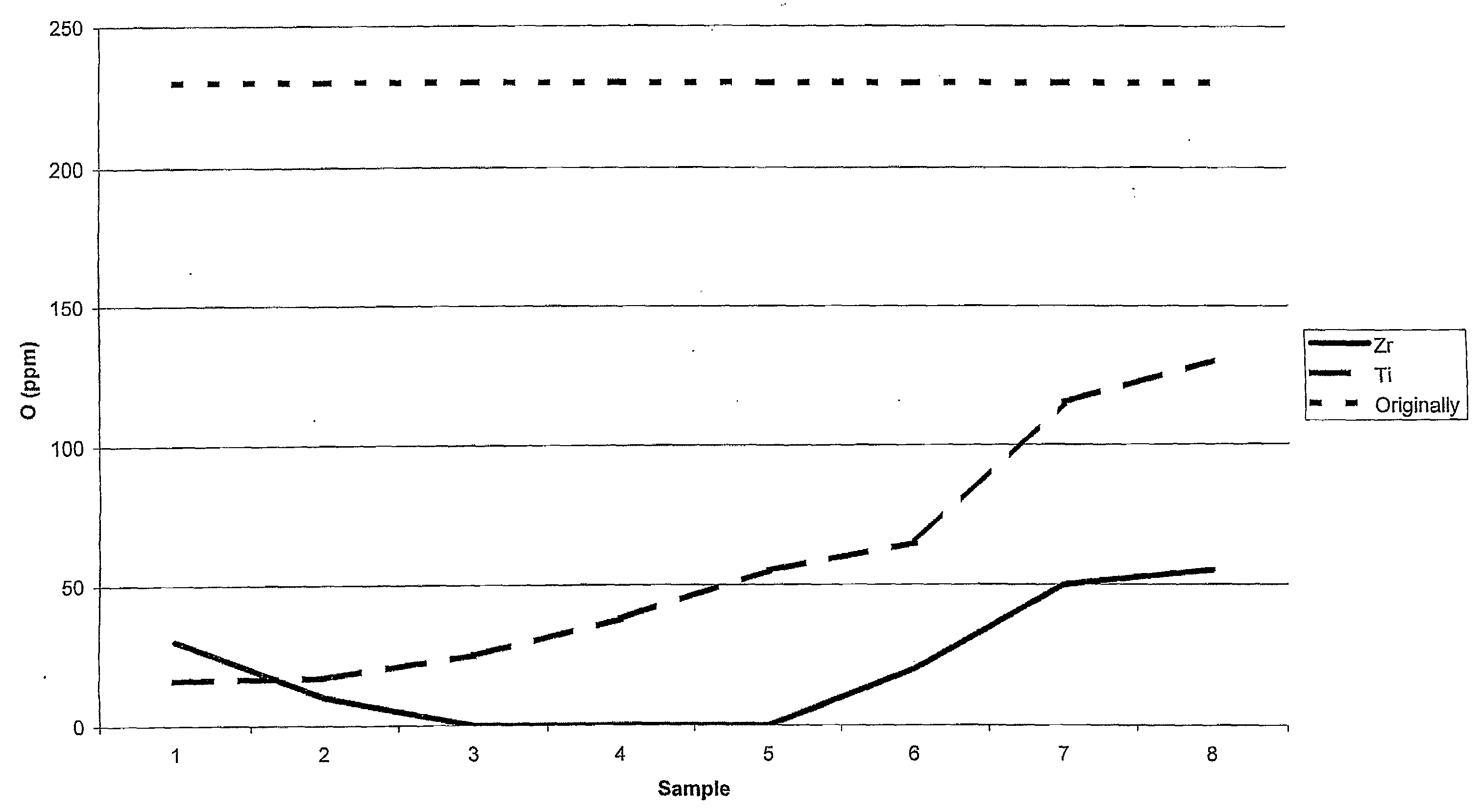
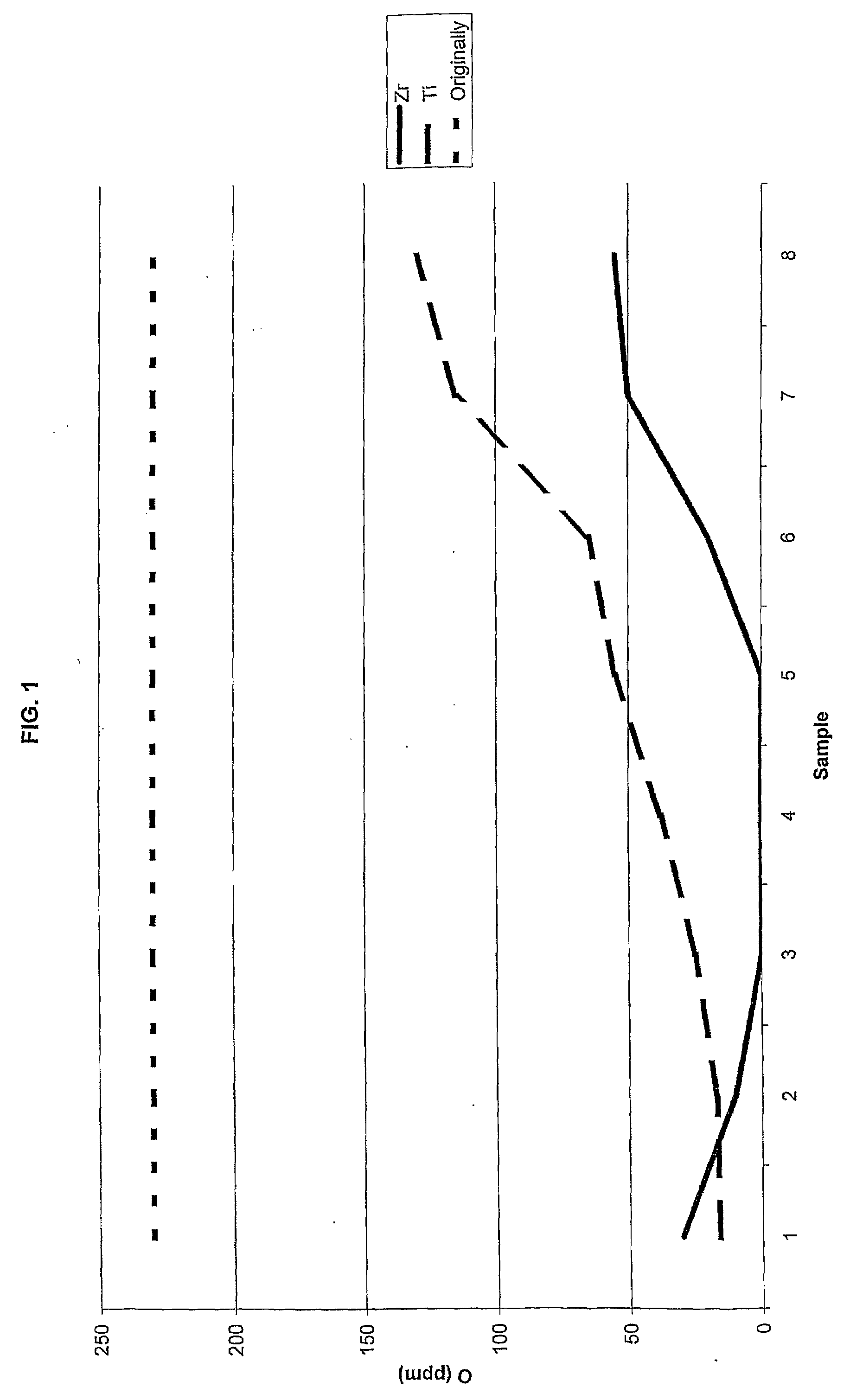
[0037]Two large canisters of 2 mm mild steel plate were produced with a diameter of 133 mm and a height of 206 mm. In this case, a 0.125 mm thick titanium foil and a 0.025 mm zirconium foil were attached to the inside of the envelope walls, respectively. The canisters were filled with Alloy 1 of Table 1, evacuated and sealed according to standard procedure. The canisters were subjected to the method described above with the following parameters: heating at 1.4° C. / min in hydrogen up to 1100° C.; holding at 1100° C. during 9 hours; changing to argon flow and slow cooling down to room temperature (The cooling rate was 1.3-1.7° C. / min down to 700° C.). Thereafter, HIP was performed at 1150° C. and 100 MPa during 3 hours.

[0038]Slices of 5 mm were cut out from the densified canisters approximately 4 cm from the top. Thereafter, eight double samples were cut out in the radial direction from the surface to the centre of the slices. The results, for the canister with Zr getter, are presente...

example 3

[0041]The impact strength of the different specimens from Examples 1 and 2 was tested along with two comparative specimens where the method was not executed. Specimens of 10×10×55 were cut out from the produced test materials. From the canister of Example 2 with Zr-foil, specimens were cut out in the radial region having approximately zero ppm oxygen.

[0042]The specimens of Alloy 2 were annealed at 1050° C. for 60 minutes and then quenched in water. Specimens of Alloy 1 were annealed at 1080° C. for 60 minutes. Some of these specimens were quenched in water and others were cooled with controlled rate of 1-2.3° C. / second through the temperature interval 900-700° C.

[0043]Notch cutting and Charpy notch impact test was performed. For the specimens of Alloy 2 the temperature of the impact tests was −196° C. and the temperature for Alloy 1 was −50° C. The results are presented in Table 5, wherein the Charpy notch impact energy is presented as an average of two specimens and Q stands for qu...


PUM

PropertyMeasurementUnit
temperatureaaaaaaaaaa
partial pressureaaaaaaaaaa

Abstract

A method of reducing the oxygen content of a powder is provided. A canister is prepared with a getter, filled with the powder to be densified, sealed and evacuated. The canister is subjected to a hydrogen atmosphere at an elevated temperature whereby hydrogen diffuses into the canister through the walls thereof. The hydroge forms moisture when reacted with the oxygen of the powder and the moisture in the reacted with the getter in order to remove oxygen from the powder to the getter. The atmosphere outside the canister is then altered to an inert atmosphere or vacuum, whereby hydrogen diffuses out of the canister. A dense body having a controlled amount of oxygen can thereafter be produced by conventional powder metallurgy techniques.

Description

[0001]The present disclosure relates to a method of reducing the oxygen content of a powder, for example a metallic powder, in a controlled manner, the powder being located in an enclosed canister. The present disclosure also relates the manufacturing of dense bodies and to a dense product produced by the method. Especially it relates to a method of reducing the oxygen content of metallic powders having high chromium content and low carbon content.BACKGROUND OF THE INVENTION AND PRIOR ART[0002]When producing powders, especially metallic powders, there is often an unintentional oxidation of the surfaces of the powders during production. Furthermore, oxygen might be present inside the powder itself, either in solution or as oxide particles. In this latter case the oxygen is usually generated during the melting process due to equilibrium with the dross and the lining of the furnace.[0003]The oxides, especially the oxides of the powder surfaces, might lead to deteriorated mechanical pro...

Claims


Application Information

Patent Timeline
Patent Type & Authority Applications(United States)
IPC IPC(8): B22F1/00B22F3/12C22C33/02B22F
CPCB22F1/0088B22F2003/1014B22F2998/00Y10T428/12014B22F3/1208B22F3/02B22F3/15
Inventor BERGLUND, ROGERERIKSSON, HANSSUNDSTROM, JOHANARVIDSSON, PER
Owner SANDVIK INTELLECTUAL PROPERTY AB
Why Eureka
Try Eureka