Heat Generating Body

a heat generation body and heat generation technology, applied in the field of heat generation bodies, can solve the problems of large dispersion of air permeability or moisture permeability, change of hole size, and difficulty in management or control, and achieve the effect of preventing water dispersion

Inactive Publication Date: 2008-11-20
MYCOAL PRODS CORP
View PDF12 Cites 33 Cited by
  • Summary
  • Abstract
  • Description
  • Claims
  • Application Information

AI Technical Summary

Benefits of technology

[0026]Then, an object of the invention is to provide a heat generating body in which a space can be surely secured in the surroundings of a heat generating compos

Problems solved by technology

However, in the case where a powdered heat generating composition is accommodated in the packing material, leakage of the powder of this heat generating composition occurs to likely stain an underwear or the skin; and in opening holes in the substrate or covering material by pin perforation, the substrate or covering material expands and contracts, and as a result, the hole size at the time of hole opening is changed, the hole size is changed with a lapse of time, or a large scatter is caused in the substantial hole size depending upon the generation state of burrs, whereby not only the air permeability or moisture permeability is largely scattered, but also the management or control thereof is extremely difficult.
Much more, in a polyolefin based resin-made film as obtained by stretching, the shape and the distribution and further the size of cracks are largely different depending upon the place in the width direction and longitudinal direction, the control is very difficult, the stability is poor, and a large scatter in the air permeability or moisture permeability is generated.
Thus, it is the present state that the management and control of the air permeability or moisture permeability, which is a very important management item in view of managing the exothermic temperature, is actually extremely difficult and that the width of the management is extremely largely scattered in the range of 20 to 30% in the plus side and the minus side, respectively against an average value thereof.
In order to make the standard width of the air permeability or moisture permeability narrower, a loss rate (20 to 30% in the existing circumstances) becomes large, resulting in high costs, and nonstandard substrates or covering materials are incorporated.
Thus, the quality management becomes remarkably troublesome.
In addition, in stretching the polyolefin based resin-made film, not only a special and expensive stretching device is needed, but also the number of steps increases and the productivity of a porous film is remarkably lowered, thereby rendering the production costs of the substrate or covering material extremely high.
Thus, there were involved various problems from the viewpoint of safety such that a required exothermic temperature is not obtained, an effective thermal effect is not obtained, and conversely, the temperature excessively rises, thereby causing a moderate-temperature burn.
For that reason, not only scattering in the air permeability leads directly to scattering in the exothermic temperature, but also since the central part of the heat generating body is smaller in heat radiation than the surroundings thereof, the temperature in the central part of the heat generating body rises as compared with that in the surroundings, resulting in an increase of danger of a moderate-temperature burn.
Thus, there was encountered a problem in view of putting it into practical use.
Thus, there were involved problems in effective use

Method used


Image

  • Heat Generating Body
  • Heat Generating Body
  • Heat Generating Body

Examples


example 1

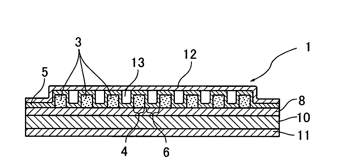
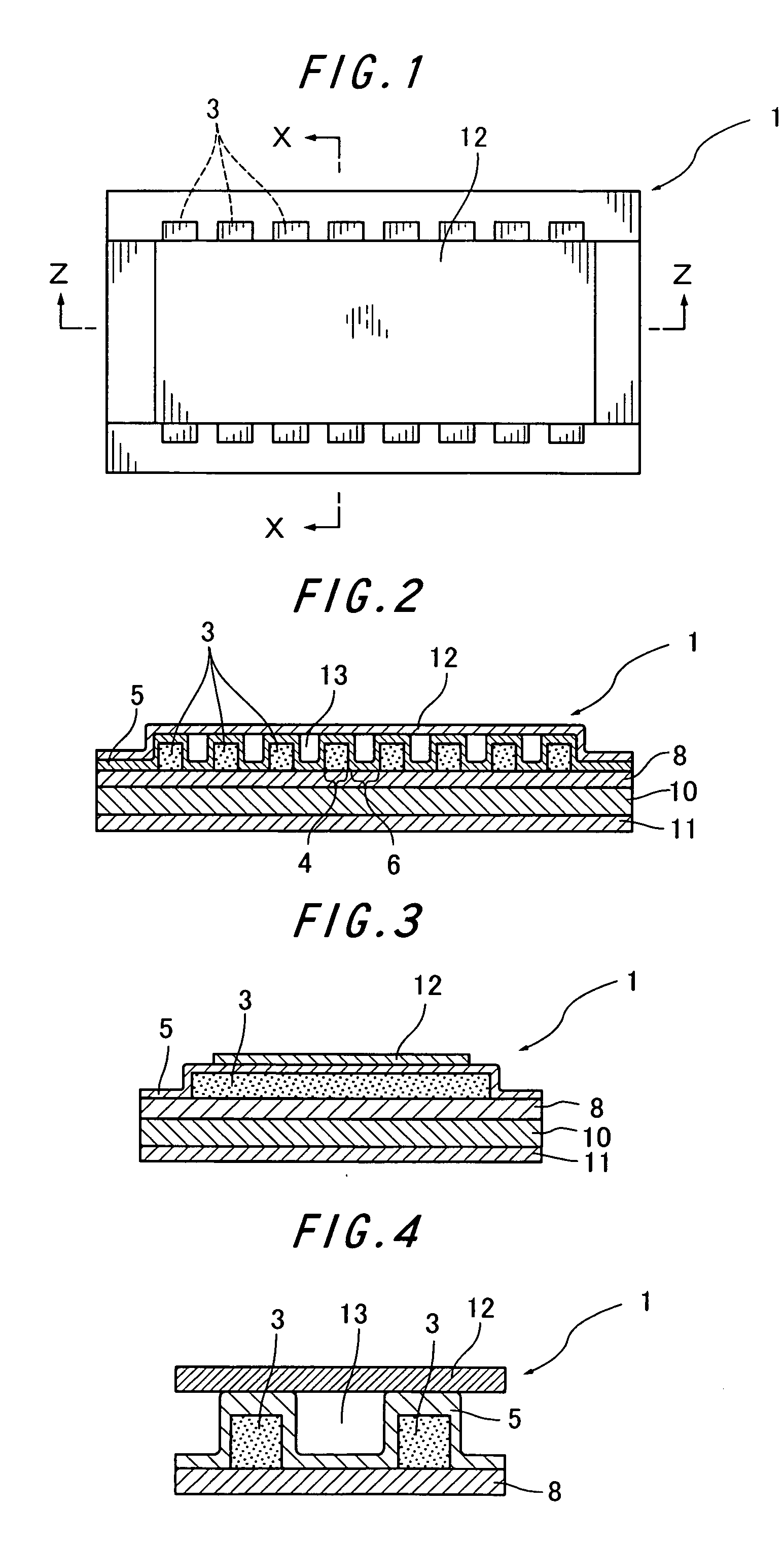
[0401]100 parts by weight of a reduced iron powder (particle size: not more than 300 μm), 7.0 parts by weight of active carbon (particle size: not more than 300 μm), 5 parts by weight of a wood meal (particle size: not more than 300 μm), 0.8 parts by weight of a water absorptive polymer (particle size: not more than 300 μm), 0.2 parts by weight of calcium hydroxide, 0.7 parts by weight of sodium sulfite (particle size: not more than 300 μm), and 11% salt water were mixed to obtain a heat generating composition having a water mobility value of 5. Next, twelve heat generating composition molded bodies of 5 mm in width×60 mm in length×2 mm in thickness were provided at intervals of 5 mm on a substrate having a separator-provided adhesive layer provided on a polyethylene film by force-through molding. Next, a covering material made of a non-woven fabric-provided polyethylene-made porous film was placed thereon such that the polyethylenes were faced at each other. The periphery of each o...

example 2

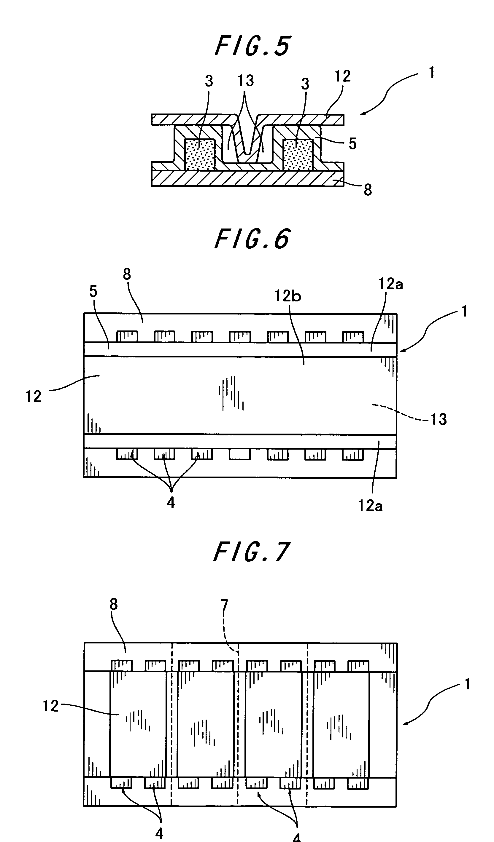
[0404]By using a heat generating body having an exothermic part made of twelve sectional exothermic parts the same as in Example 1, an air permeability adjusting material made of a polyethylene film of 50 mm in width×135 mm and having a bonding layer constituted of an adhesive provided in the both sides thereof in a width of 10 mm was stuck on the foregoing non-woven fabric while leaving both ends of the sectional exothermic part in a width of 5 mm, thereby obtaining a heat generating body.

[0405]The peripheries of 10 mm in the both ends of the sectioned part of this heat generating body are formed as an air intake; and the air permeability adjusting material and the sectional exothermic part are not adhered in the central part of the heat generating body, whereby a spacial air-permeable layer made of a spacial part crossing the respective sectional exothermic parts is formed.

[0406]This heat generating body was sealed and accommodated in an air-impermeable outer bag and allowed to st...

example 3

[0407]A batchwise stirring tank composed of a mixer equipped with a stirring blade was used as an oxidizing gas treatment device, and air was used as an oxidizing gas. A reaction mixture consisting of 100 parts by weight of a reduced iron powder (particle size: not more than 300 μm), 5.3 parts by weight of active carbon (particle size: not more than 300 μm), 5 parts by weight of a wood meal (particle size: not more than 300 μm), 0.8 parts by weight of a water absorptive polymer (particle size: not more than 300 μm), 0.2 parts by weight of calcium hydroxide (particle size: not more than 300 μm), 0.7 parts by weight of sodium sulfite (particle size: not more than 300 μm), and 5 parts by weight of 11% salt water and having a water mobility value of not more than 0.01 was charged in the device vessel. Next, in the state that the device vessel as adjusted at 20° C. was opened to air, the reaction mixture was treated with an oxidizing gas while stirring for 3 minutes to obtain a heat gene...


PUM


Abstract

To provide a heat generating body in which a space can be surely secured in the surroundings of a heat generating composition and heat insulation of the heat generating composition, adjustment of the quantity of air to be taken in and prevention of dispersion of water can be achieved.
A heat generating body having an exothermic part having a heat generating composition molded body which is a molded body of a heat generating composition capable of causing heat generation upon contact with air in a convex of an accommodating bag having plural irregularities by laminating the heat generating composition molded body on a substrate, covering a covering material thereon and then heat sealing the periphery of the heat generating composition molded body, characterized in that the heat generating composition contains, as essential components, an exothermic substance, a carbon component, a reaction accelerator and water; that the heat generating body is composed of a sectional exothermic part and a sectioned part, the sectional exothermic part accommodates the heat generating composition molded body therein, the sectioned part is a seal part, and the sectional exothermic part is disposed via the sectioned part; that at least a part of the sectional exothermic part has an air-permeable surface; that the air-permeable surface which comes into contact with the heat generating composition molded body is constituted of a non-water absorptive raw material; that the sectional exothermic part and the sectioned part have a difference of altitude, and the part having a difference of altitude is covered by an air permeability adjusting material via a bonding layer and forms a partitioned spacial part; and that the spacial part is provided with a primary air intake.

Description

TECHNICAL FIELD[0001]The present invention relates to a heat generating body which equalizes and efficiently reveals expected reaction heat of a heat generating composition, makes the whole of an exothermic part of the heat generating body warm within a short period of time, controls the movement of a gas from the heat generating composition by an air permeability adjusting material and a spacial air-permeable layer, minimizes influences of a change of the outside air temperature, effectively achieves heat insulation of the heat generating composition to prevent a lowering of the temperature of the heat generating composition per se due to an inflow of cold outside air from occurring, uniformly achieves an exothermic reaction, eliminates going out of the exothermic reaction, is small in scattering of the temperature, achieves the heat generating over a long period of time, and is excellent in temperature characteristics.BACKGROUND ART[0002]In the production of a heat generating body...

Claims


Application Information

Patent Timeline
IPC IPC(8): F24J1/00C09K5/16F24V30/00
CPCA61F7/034A61F2007/0098A61F2007/0268C09K5/18F24J1/00F24V30/00
Inventor DODO, TOSHIHIRO
Owner MYCOAL PRODS CORP
Why Eureka
Try Eureka