Ultrasonic Cleaning Method and Device

a cleaning method and ultrasonic technology, applied in the direction of cleaning using liquids, mechanical vibration separation, separation processes, etc., can solve the problems of chronic toxicity of glutaraldehyde, the sterilization method using high-pressure steam cannot be used for endoscopes or other appliances that are not suitable for high-temperature processing, and the process is complicated

Inactive Publication Date: 2008-11-27
KAGOSHIMA SUPERSONIC TECHN LAB
View PDF3 Cites 41 Cited by
  • Summary
  • Abstract
  • Description
  • Claims
  • Application Information

AI Technical Summary

Benefits of technology

[0010]Medical waste water ejected from a large scale hospital or the like in a quantity over an emission regulation must be processed individually before being discharged to a public sewerage or a river because it contains a lot of organic matters that increase BOD (Biochemical Oxygen Demand). In many cases, a process of the medical waste water uses a method of decreasing the BOD with an activated sludge facility for decomposing organic matters such as a detergent by using microorganisms. However, if waste water of washing hands that has a bactericidal effect is mixed a lot

Problems solved by technology

The conventional method for cleaning and sterilizing medical appliances needs three process steps including the precleaning step using the enzyme treatment, the ultrasonic cleaning step and the sterilization step, and its process is complicated.
In addition, the sterilization method by using the high-pressure steam cannot be used for an endoscope or other appliance that is not suitable for high temperature processing.
The gas s

Method used


Image

  • Ultrasonic Cleaning Method and Device
  • Ultrasonic Cleaning Method and Device
  • Ultrasonic Cleaning Method and Device

Examples


first embodiment

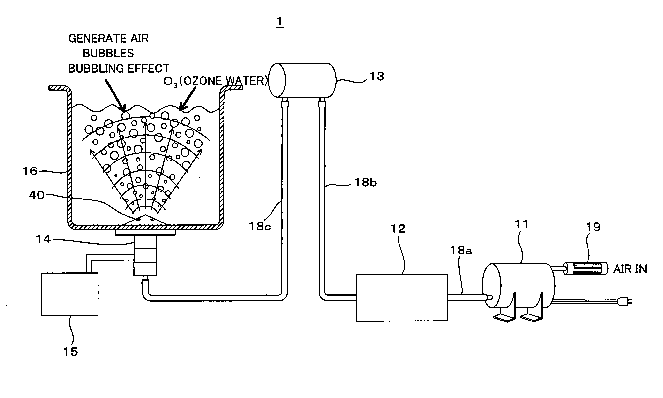
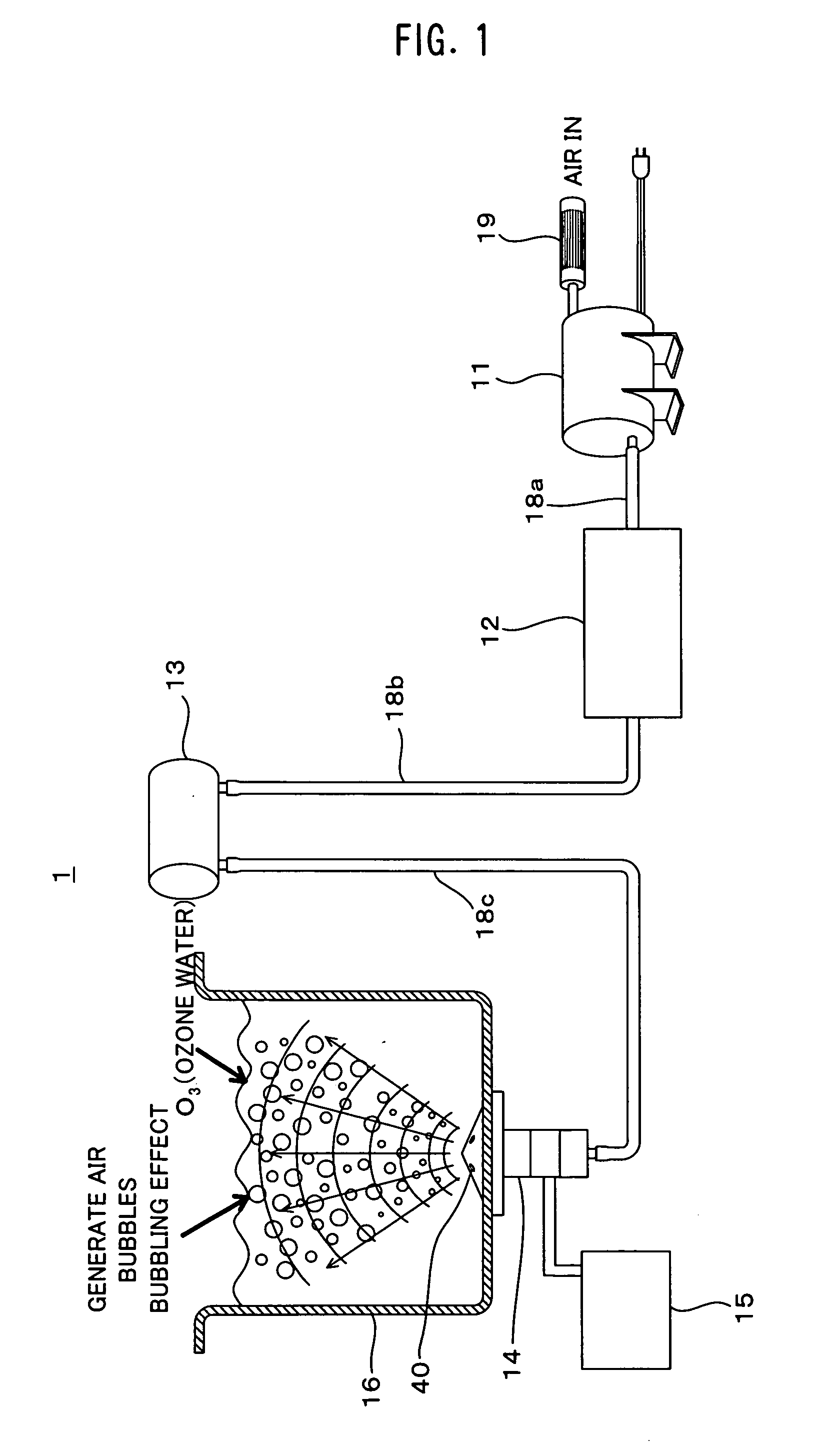
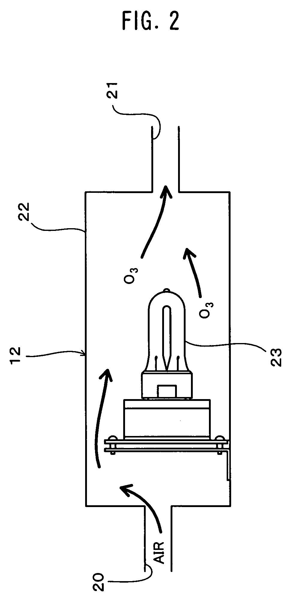
[0030]FIG. 1 is a diagram showing a structure of an ultrasonic cleaning device 1 according to a first embodiment of the present invention, FIG. 2 is a diagram showing a structure of an ozone generation device 12, FIG. 3 is a front cross section of an ultrasonic vibration transducer 14, FIG. 4 is a plan view of the ultrasonic vibration transducer 14, FIG. 5 is a perspective view showing the ultrasonic vibration transducer 14 in an exploded manner, FIG. 6 is a perspective view of the ultrasonic cleaning device 1, and FIG. 7 is a diagram showing an arrangement of the ultrasonic vibration transducers 14 in the ultrasonic cleaning device 1.

[0031]In FIGS. 1-7, the ultrasonic cleaning device 1 is made up of a compressor 11, the ozone generation device 12, a buffer tank 13, an ultrasonic transducer 14, a drive portion (a drive circuit) 15 and a cleaning tank 16. As shown in FIG. 6, the compressor 11, the ozone generation device 12, the buffer tank 13, the ultrasonic transducer 14, the drive...

second embodiment

[0053]FIG. 8 is a side cross section of a cleaning tank 16B with ultrasonic transducers 14Ba and 14Bb of an ultrasonic cleaning device 1B according to a second embodiment of the present invention, and FIG. 9 is a front cross section of the ultrasonic cleaning device 1B shown in FIG. 8.

[0054]The ultrasonic cleaning device 1B according to the second embodiment includes the ultrasonic transducers 14Ba and 14Bb and the cleaning tank 16B shown in FIG. 8, and it further includes a compressor, an ozone generation device, a buffer tank and a drive portion. Since they are the same as those of the ultrasonic cleaning device 1 according to the first embodiment, so descriptions thereof will be omitted. In addition, the structure of the ultrasonic transducers 14Ba and 14Bb is the same as that of the ultrasonic cleaning device 1, so the description of the ultrasonic transducers 14Ba and 14Bb are also omitted. Note that a suffix B may be added to reference numerals in the second embodiment like th...

third embodiment

[0061]FIG. 10 is a side cross section of a cleaning tank 16C of an ultrasonic cleaning device 1C with ultrasonic transducers 14Ca-14Cc attached according to a third embodiment of the present invention, and FIG. 11 is a front cross section of the ultrasonic cleaning device 1C shown in FIG. 10.

[0062]As shown in FIGS. 10 and 11, the ultrasonic transducers 14Ca-14Cc are attached on a bottom portion 45C of the cleaning tank 16C so that four transducers are aligned on each of two lines and on two opposed side walls 46Ca and 46Cb so that four transducers are aligned on one line of each side (horizontal and vertical trident interference type). The ultrasonic transducers 14Ca in two lines on the bottom portion 45C and the ultrasonic transducers 14Cb and 14Cc on the side walls 46Ca and 46Cb are arranged so that four axes of the four transducers are aligned on the plane that is perpendicular to each of the bottom portion 45C and the two side walls 46Ca and 46Cb. The eight ultrasonic transducer...


PUM

PropertyMeasurementUnit
Poweraaaaaaaaaa
Electric potential / voltageaaaaaaaaaa
Circumferenceaaaaaaaaaa

Abstract

An ultrasonic cleaning method and an ultrasonic cleaning device are provided, which are capable of performing simultaneously cleaning and sterilization of medical appliances or the like, and which can also be used for washing hands for disinfection without any special waste water treatment. The ultrasonic cleaning method for cleaning an object to be cleaned by using an ultrasonic wave includes the steps of putting cleaning fluid and the object to be cleaned in a cleaning tank (16), and applying ultrasonic vibrations to the cleaning fluid from an ultrasonic vibration member disposed in the cleaning tank (16) while ejecting air containing ozone into the cleaning fluid. The vibration portion has a communicating conduit 40 that opens at the surface thereof, and air containing ozone is discharged into the cleaning fluid from the communicating conduit. A silver electrode is disposed in the cleaning fluid, and electrolytic sterilization by silver ions is performed for the object to be cleaned adding to sterilization by ozone.

Description

TECHNICAL FIELD[0001]The present invention relates to an ultrasonic cleaning method and an ultrasonic cleaning device for cleaning an object by applying ultrasonic vibration to a cleaning fluid inside a cleaning tank.BACKGROUND ART[0002]Conventionally, medical appliances such as scissors and forceps that were used for an operation or a therapy in a hospital or the like are cleaned or sterilized by the following methods.[0003](1) Removal of blood or the like by using hot water or an enzyme treatment (hereinafter referred to as a “precleaning”).[0004](2) Ultrasonic cleaning by using a detergent.[0005](3) Sterilization by using an autoclave with high-pressure steam at a temperature of 135 degrees centigrade, gas sterilization by using ethylene oxide gas, or sterilization by dipping in 2% glutaraldehyde solution.[0006]In addition, clothes such as a white garment are sterilized by using high-pressure steam after a usual laundry for removing dirty things.[0007]The devices as mentioned abo...

Claims


Application Information

Patent Timeline
IPC IPC(8): C25F1/00B08B3/12C25F7/00B08B13/00
CPCA61B19/34A61B2019/343A61C19/002A61L2/025A61L2/035A61L2/202B08B3/12A61B90/70A61B2090/701A61L2/18B06B1/00
Inventor SHIGIHARA, TAKANORIUEDA, TOYOTOSHI
Owner KAGOSHIMA SUPERSONIC TECHN LAB
Why Eureka
Try Eureka