

Apparatus and method for computing 3D ultrasound elasticity images
- Summary
- Abstract
- Description
- Claims
- Application Information
AI Technical Summary
Benefits of technology
Problems solved by technology
Method used
Image

Examples
Embodiment Construction
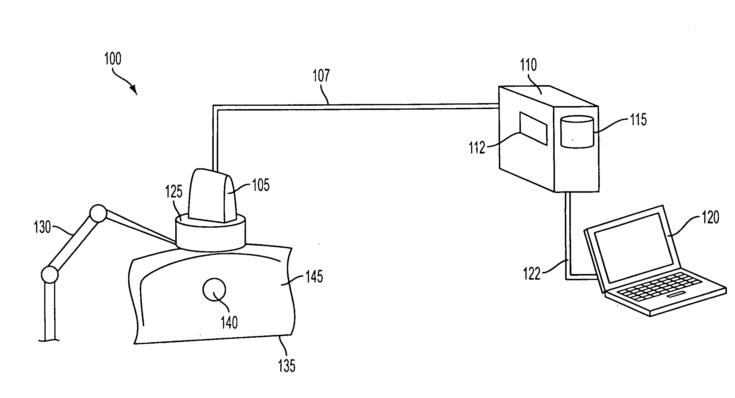
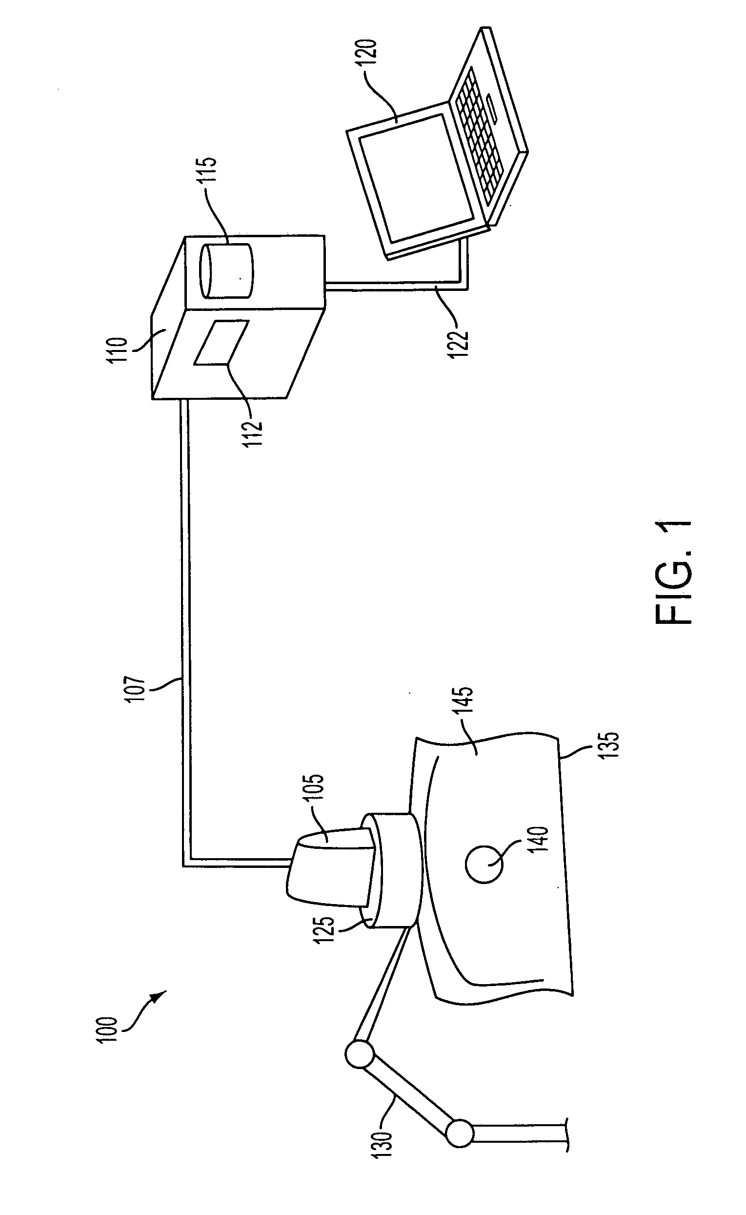
[0036]FIG. 1 illustrates an exemplary system 100 for computing 3D ultrasound elasticity images. System 100 includes an ultrasound probe 105, which communicates with a computer 110 over a signal cable 107. Computer 110 may have a processor 112 and a memory 115. Computer 100 may also have a user interface 120, which may be integrated into computer 120, or may be a separate computer that communicates with computer 110 over a network connection 122.
[0037]System 100 may also include an optional ultrasound probe mount 125, which may be connected to a mechanical arm 130. Mechanical arm 130, which is optional, may be a robotic arm that is controlled by computer 110, or a passive arm that serves to stabilize probe mount 125. In the latter case, ultrasound probe 105 and probe mount 125 may be moved (translated and rotated) manually by a technician.
[0038]Ultrasound probe 105 may be a commercially available ultrasound probe. And ultrasound probe 105, computer 110, and user interface 120 may be ...
PUM
 Abstract
Description
Claims
Application Information