

Scanning electron microscope and method of imaging an object by using the scanning electron microscope
a scanning electron microscope and scanning electron technology, applied in material analysis using wave/particle radiation, instruments, nuclear engineering, etc., can solve the problems of long time taken to perform switching operations, deterioration of reproducibility, and varied magnetic field, and achieve high reproducibility, high resolution, and high speed
- Summary
- Abstract
- Description
- Claims
- Application Information
AI Technical Summary
Benefits of technology
Problems solved by technology
Method used
Image

Examples
first embodiment
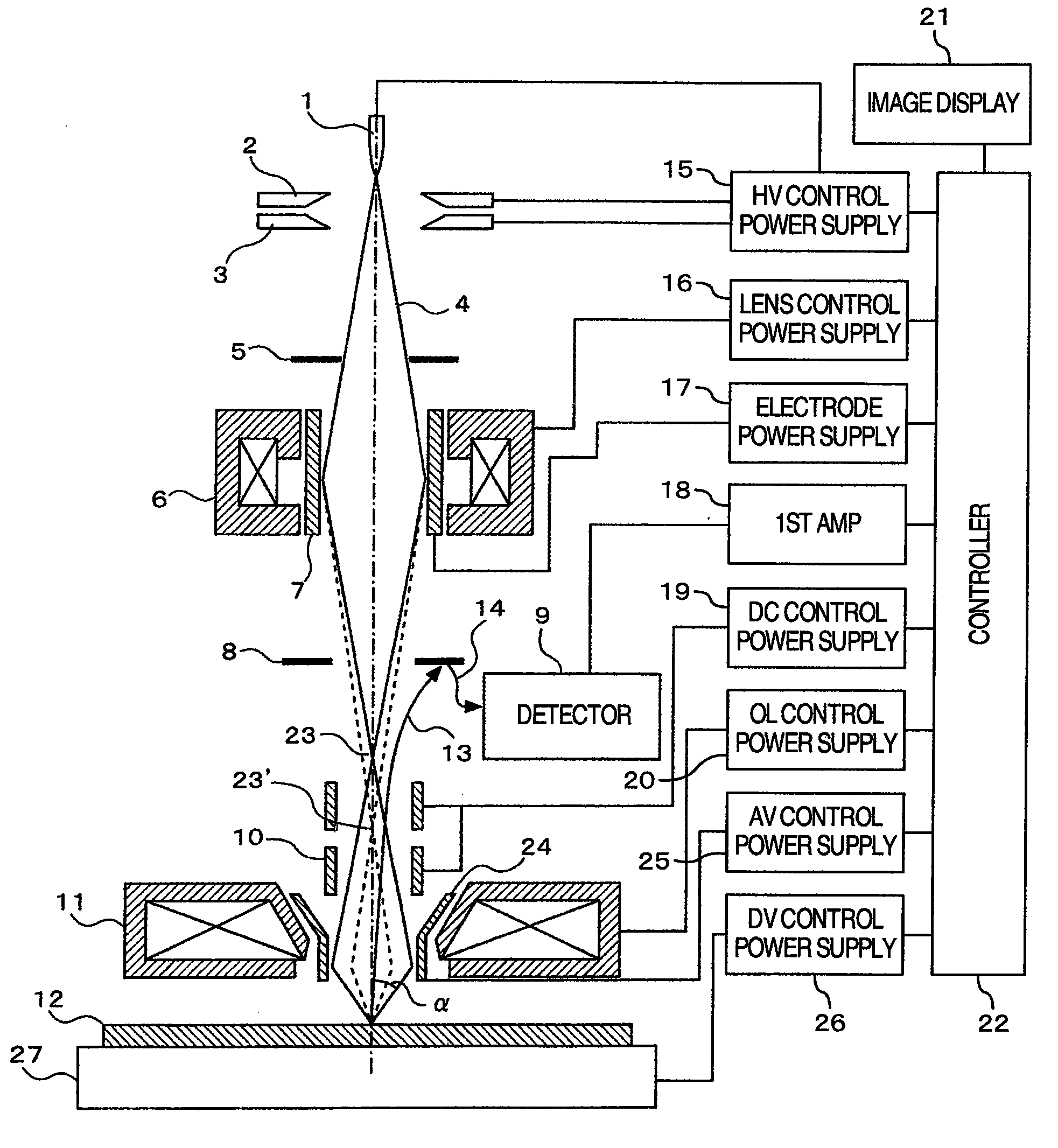
[0019]FIG. 1 is a schematic cross-sectional view showing the structure of a scanning electron microscope according to the present invention. In the figure, a vacuum vessel, a wafer-conveying system, and so on necessary for the scanning electron microscope are omitted. A voltage is applied between a cathode 1 and a first anode 2 from a high-voltage (HV) control power supply 15 that is under control of a controller 22. A given emission current is extracted from the cathode 1. An accelerating voltage is applied between the cathode 1 and a second anode 3 from the high-voltage control power supply 15 that is under control of the controller 22. Therefore, a primary electron beam 4 released from the cathode 1 is accelerated toward a rear stage of lenses. After undesired regions of the primary electron beam 4 are removed by an aperture plate 5, the beam 4 is focused at a focal position 23 by a condenser lens 6 that is under control of a lens control power supply 16.
[0020]Then, the primary e...
second embodiment
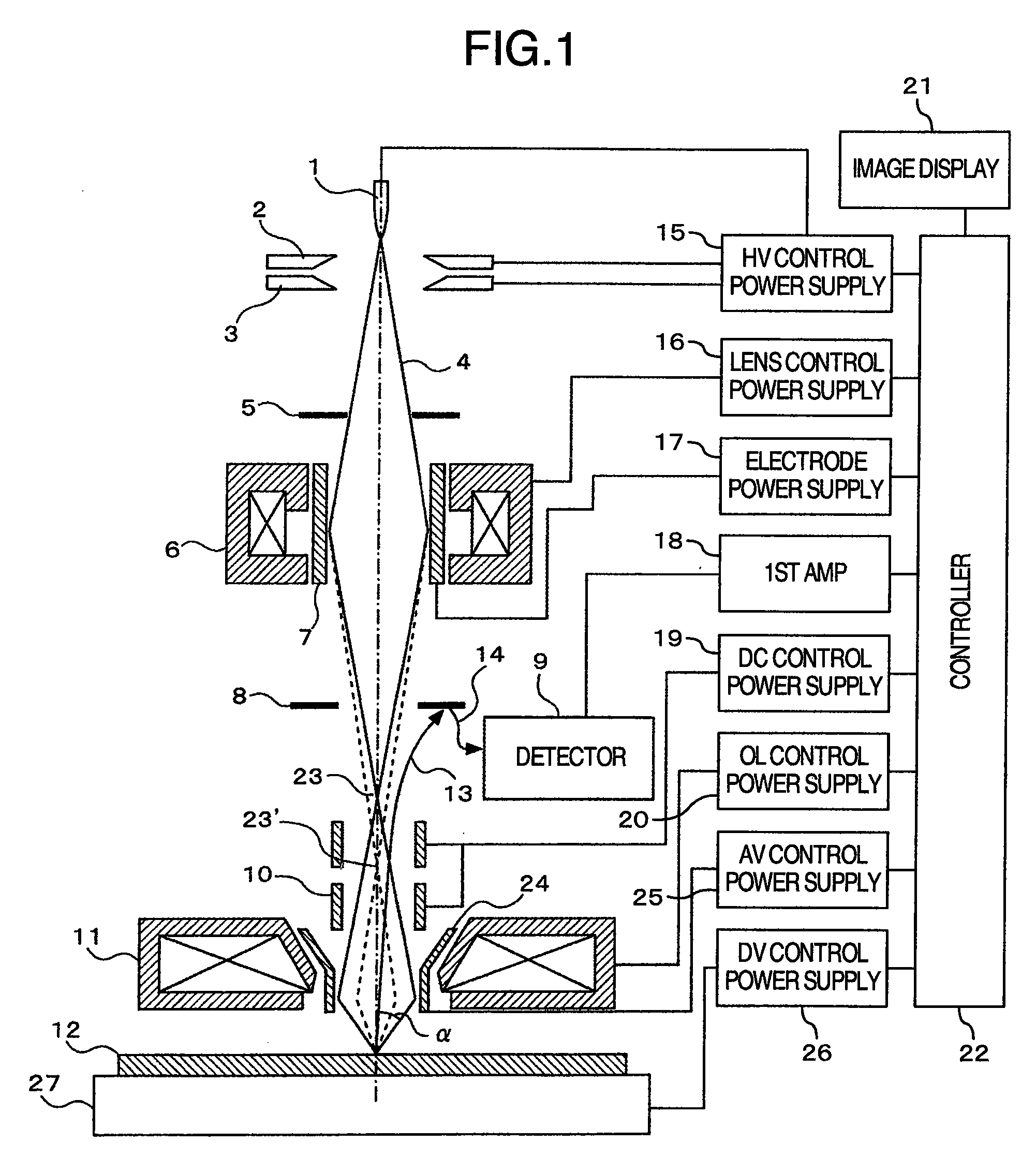
[0029]FIG. 3 is a vertical cross section showing the structure of a scanning electron microscope according to the present invention. This structure is similar to the structure already described in connection with FIG. 1 except that the condenser lens 6 of FIG. 1 is replaced by two stages of condenser lenses consisting of a first condenser lens 6a and a second condenser lens 6b that are controlled by lens control power supplies 16a and 16b. respectively. The aperture plate 5 is disposed between the first condenser lens 6a and the second condenser lens 6b to remove regions not necessary for formation of an image from the primary electron beam 4. Then, the beam is converged by the second condenser lens 6b and focused into a very small spot onto the specimen 12 by the objective lens 11 that is under control of the objective lens control power supply 20. The amount of the primary electron beam 4 passed through the aperture plate 5 is adjusted by controlling the focal position 23 of the f...
third embodiment
[0031]FIG. 4 is a vertical cross section showing the structure of a scanning electron microscope according to the present invention. This structure is characterized in that an axisymmetric electrode 7b is disposed within the magnetic field generated by the second condenser lens 6b shown in FIG. 3. The aperture angle α is determined by the focal position 23a of the first condenser lens 6a, the diameter of the aperture in the aperture plate 5, and the focal position 23b of the second condenser lens. When a voltage is applied to the axisymmetric electrode 7a disposed within the magnetic field set up by the first condenser lens 6a from an electrode power supply 17b, the focal position 23a of the first condenser lens 6a varies, thus changing the amount of the primary electron beam 4 impinging on the specimen 12. However, the aperture angle α also varies because the focal position 23a of the first condenser lens 6a varies. Accordingly, the aperture angle α can be controlled by applying a ...
PUM
 Abstract
Description
Claims
Application Information