Method for Making a Material

Inactive Publication Date: 2008-12-18
VERY SMALL PARTICLE CO LTD
View PDF5 Cites 23 Cited by
  • Summary
  • Abstract
  • Description
  • Claims
  • Application Information

AI Technical Summary

Benefits of technology

[0095]The heating step may involve a rapid heating to the maximum desired temperature, or it may involve a much more closely controlled heat treatment regime. For example, the heating step may be carried out under a controlled atmosphere. The heating step may involve heating to a drying temperature (generally below the boiling temperature of the mixture) to dry the mixture, followed by a slow ramp up to the maximum applied temperature, or followed by a series of incremental increases to intermediate temperatures before ultimately reaching the maximum applied temperature. The duration of the heating step may vary widely, with a preferred time in step (c) being from 15 minutes to 24 hours. It will be appreciated that step (b) is intended to encompass all heating profiles that result in the formation of metal oxide phases.
[0096]The heating step (b) of the present invention encompasses all such heating steps that result in the formation of the desired metal oxide. The heating step may be carried out using heating apparatus known by the person of skill in the art to be suitable for such purposes. Examples include hot plates or other heated substrates, ovens, stationary table furnaces, rotary table furnaces, induction furnaces, fluid bed furnaces, bath furnaces, flash furnaces, tube furnaces, infrared furnaces, muffle furnaces, drop furnaces, belt furnaces, rotary furnaces, rotary kilns, rotary dryers, spray dryers, spin-flash dryers, drum dryers, reaction vessels, and flash calciners.
[0097]The present invention may also be practised by preparing a mixture of a metal cation-containing solution and a hydrophilic polymer and the support particles and subsequently heating the mixture to form metal oxide deposited on or supported on the support particles

Problems solved by technology

For example, the most catalytically active material for a particular application may be prohibitively expensive.
The supported catalyst may be difficult to manufacture, or it may degrade (i.e. lose its catalytic activity) over time.
Degradation of catalytic performance may arise due to poisoning of the catalytic material, loss of catalytic material from the support (such as by leaching, erosion or abrasion) or by loss of surface area due to diffusion and growth of the catalytic material at elevated temperatures.
Indeed, claim 1 of Sturmann et al is limited to a reasonably complex support composition containing SiH-groups.
Noble metals are extremely high cost and high catalyst attrition rates in given chemical process can negate the choice of noble metals as a preferred catalyst for that process.
According to Zhou et al, their high cost also requires that their superior catalytic activity be sufficiently high compared to other catalyst choices to justify their use.
However, the high surface energy of the small particles

Method used


Image

  • Method for Making a Material
  • Method for Making a Material

Examples


example 1

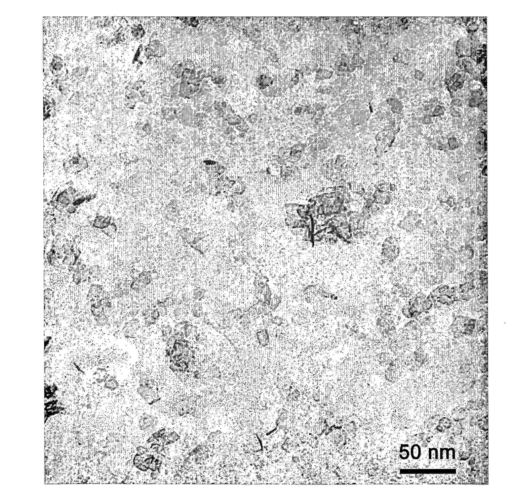
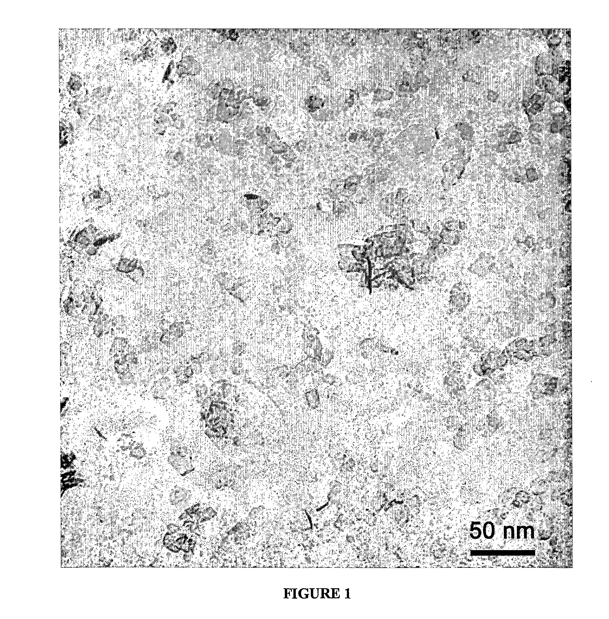
[0100]A composition 20 wt % Ce0.53Zr0.37Pr0.06La0.04Ox on alumina was prepared in the following manner. Cerium nitrate hexahydrate, zirconium carbonate, lanthanum nitrate hexahydrate and praseodymium nitrate hexahydrate were dissolved in the appropriate proportions to make 4.5 g of Ce0.537Zr0.375La0.025Pr0.063O, in ˜15 g water. 27 g of boehmite (aluminum hydroxide) plate-shaped nanoparticles (Sasol, Dispal 23-N4 80) was dispersed in 200 g water. FIG. 1 shows a TEM photomicrograph of such a plate-shaped nanoparticle. The salt solution was added to the boehmite dispersion, then 16 g of carbon black (Raven 850, Columbian Chemicals) and mixed with a high-speed stirrer. 47 g of surfactant (Erunon LA4) was added and mixed. This final mixture was heated slowly to a temperature of 500° C., and then higher temperature testing was carried out for 2 h at 1000° C.

Following the heat treatment to 1000° C., XRD showed a ceria-containing phase and alumina. TEM showed the structure consisted of nano...

example 2

[0101]A composition 20 wt % Ce0.53Zr0.37Pr0.06La0.04Oxon alumina was prepared in a similar manner to example 1, except that polyethylene glycol was used instead of LA4 surfactant.

Following the heat treatment to 1000° C., XRD showed a ceria-containing phase and alumina. TEM showed the structure consisted of nano-sized particles of the catalyst phase dispersed throughout the alumina. The surface area was 103 m2 / g, and the pore volume for pores between 2 nm and ˜200 nm was 0.89 cc / g.

example 3

[0102]A composition 20 wt % Ce0.53Zr0.37Pr0.06La0.04Ox on alumina was prepared in a similar manner to example 1, except that DISPAL 18BP was used instead of X-O.

Following the heat treatment to 1000° C., XRD showed a ceria-containing phase and alumina. TEM showed the structure consisted of nano-sized particles of the catalyst phase dispersed throughout the alumina. The surface area was 87.5 m2 / g, and the pore volume for pores between 2 nm and ˜200 nm was 0.66 cc / g.


PUM

PropertyMeasurementUnit
Grain sizeaaaaaaaaaa
Temperatureaaaaaaaaaa

Abstract

The invention relates to a method for forming a material of a metal oxide supported on a support particle by the steps of. a) providing a precursor mixture comprising a solution containing one or more metal cations and (i) a surfactant; or (ii) a hydrophilic polymer; with the precursor mixture further including support particles; and b) treating the precursor mixture from (a) above by heating to remove the surfactant or hydrophilic polymer and form metal oxide having nano-sized grains, wherein at least some of the metal oxide formed in step (b) is deposited on or supported by the support particles and the metal oxide has an oxide matrix that includes metal atoms derived solely from sources other than the support particles.

Description

FIELD OF THE INVENTION[0001]The present invention relates to a method for making a material. The present invention particularly relates to a method for making a material in which a metal oxide material is supported on a support. The metal oxide material may be catalytically active.BACKGROUND TO THE INVENTION[0002]Catalysts are widely used in a large number of industries. Some examples of industries that utilise catalysts include oil refining (especially cracking and reforming), automotive manufacture (especially exhaust catalysts, such as three way catalysts), plastics manufacturing, production of synthesis gas, chemical synthesis processors, absorption and fuel cell manufacture.[0003]A wide range of catalysts are of the type known as supported catalysts. In these catalysts, a catalytic material is supported on a support substrate. The support substrate may be in the form of powder, particles or monoliths. The support substrate is normally selected on the basis of the substrate bein...

Claims


Application Information

Patent Timeline
IPC IPC(8): B01J21/16B01J23/02B01J23/04B01J23/06B01J23/10B01J23/20B01J23/26B01J23/28B01J21/06B01J29/00B01J23/34B01J23/36B01J23/40B01J23/42B01J23/44B01J23/50B01J23/52
CPCB01J23/002B01J23/10B01J23/63B01J35/0013B01J35/0093B01J35/1042B01J37/0018B01J37/0236B01J37/036B01J2523/00H01M4/9016H01M4/9075Y02E60/50B01J2523/31B01J2523/3706B01J2523/3712B01J2523/3718B01J2523/48B01J2523/23B01J2523/24B01J2523/3725B01J2523/22B01J2523/72
Inventor TALBOT, PETER CADEEDWARDS, GEOFFREY ALANALARCO, JOSE ANTONIO
Owner VERY SMALL PARTICLE CO LTD
Why Eureka
Try Eureka