
Light-transmitting module capable of responding a high-frequency over 10GHz

a technology of light-transmitting modules and high-frequency response, which is applied in the direction of lasers, semiconductor laser structural details, semiconductor lasers, etc., can solve problems such as unstable operation of driving circuits, and achieve the effect of enhancing the high-frequency performance of light-transmitting modules

Inactive Publication Date: 2009-01-01
MOTO AKIHIRO
View PDF9 Cites 12 Cited by
  • Summary
  • Abstract
  • Description
  • Claims
  • Application Information

AI Technical Summary

Benefits of technology

The present invention relates to a light-transmitting module that includes a metallic block, an insulating heat sink, an electrically conductive layer, and a laser diode. The heat sink is mounted on the block and the conductive layer is provided on the heat sink to form a parallel-plate capacitor. The laser diode is mounted on the conductive layer with the anode facing and in contact with the conductive layer. The capacitance of the parallel-plate capacitor is preferably at least 50 pF. The invention enhances the high frequency performance of the laser diode even at an operational frequency over 10 Gbps. The heat sink may also include a V-groove for securing an optical fiber therein and another groove for securing an ferrule in which the optical fiber inserted. The light-transmitting module may further include a driver for driving the laser diode. The driver is preferably mounted on the conductive block or the heat sink to shorten the electrical connection between the driver and the laser diode, thereby enhancing the high frequency performance of the light-transmitting module.

Problems solved by technology

When the critical frequency closes to the transmission frequency, the driving circuit will operate in unstable.

Method used


Image

  • Light-transmitting module capable of responding a high-frequency over 10GHz
  • Light-transmitting module capable of responding a high-frequency over 10GHz
  • Light-transmitting module capable of responding a high-frequency over 10GHz

Examples


first embodiment

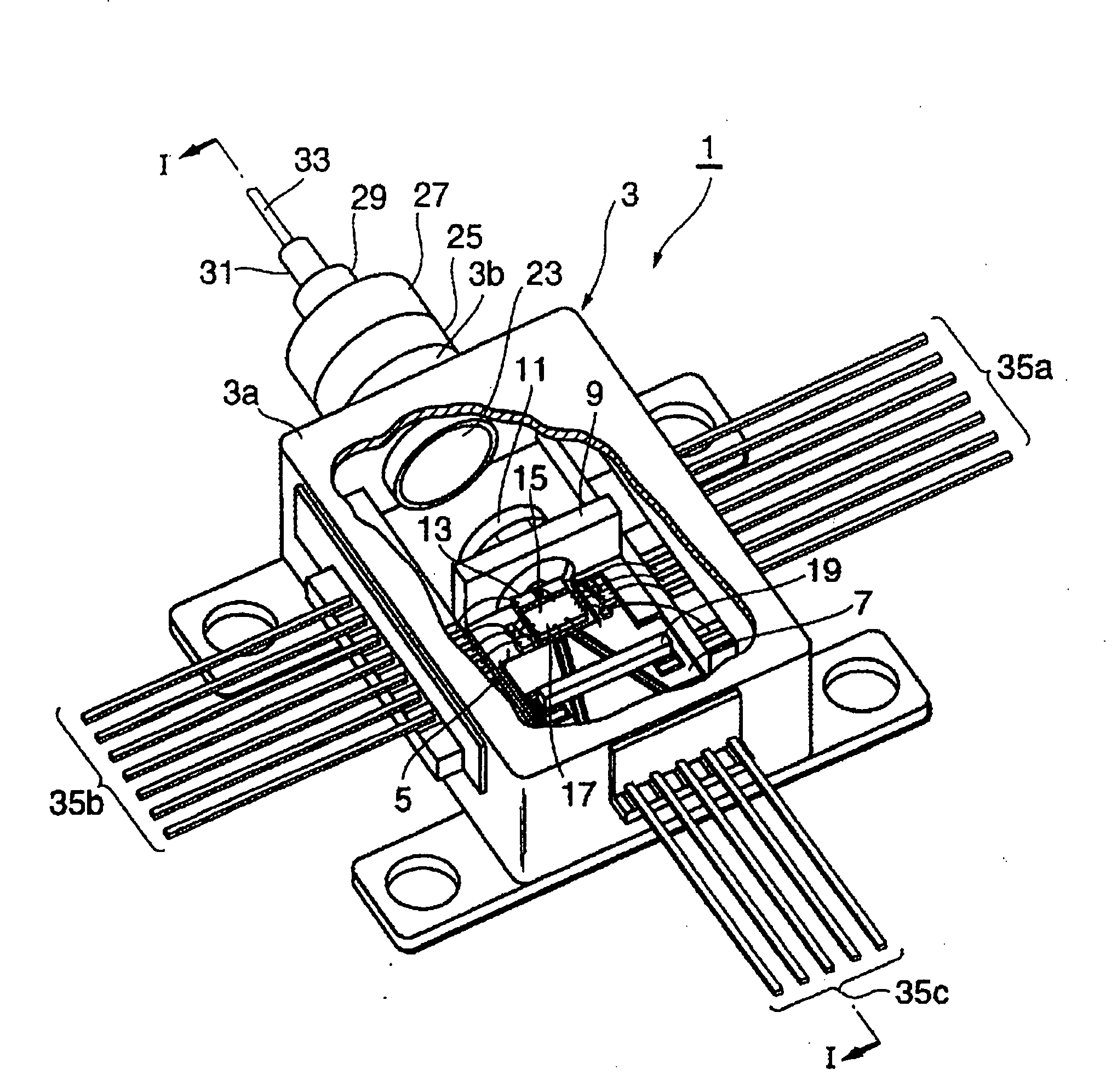
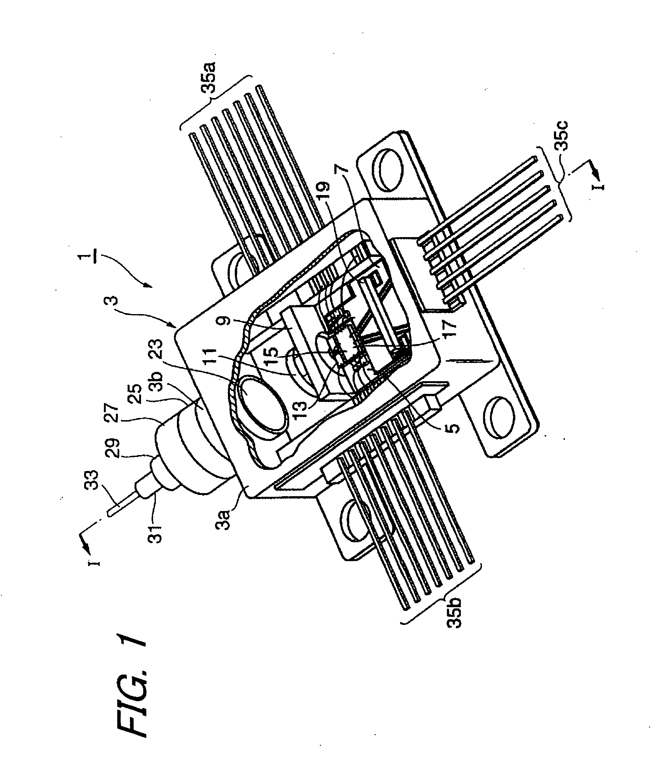
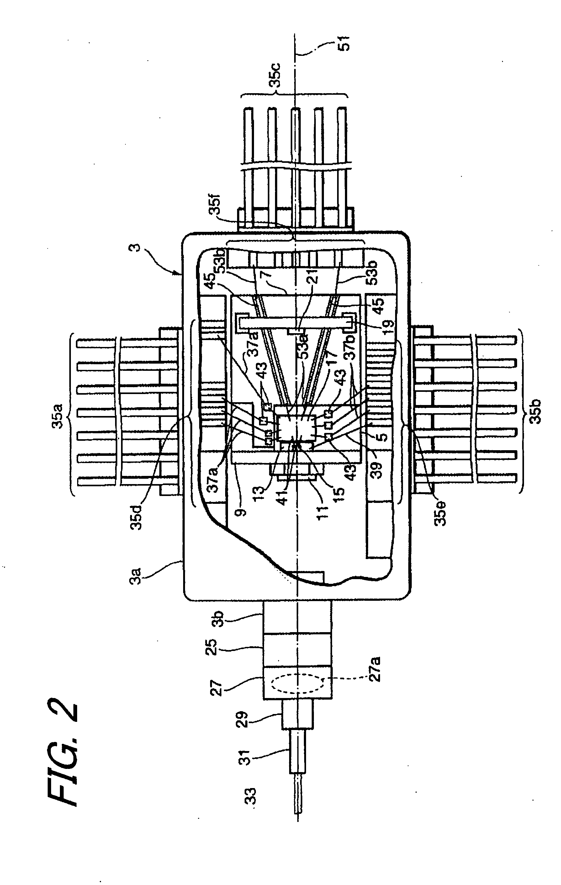
[0028]From FIG. 1 to FIG. 3 show a light-transmitting module 1 according to the first embodiment of the present invention, FIG. 1 is a perspective view, FIG. 2 is a plan view and FIG. 3 is a cross sectional view along the lint I-I in FIG. 1, respectively.

[0029]The light-transmitting module 1 includes a package 3, a first block 5, a substrate 7, a heat sink 13, a laser diode 15 and a driver 17. The package 3, so-called a butterfly type package, has a box portion 3a enclosing the laser diode 15 and the driver 17 and a cylindrical portion 3b provided in the front side of the box portion 3a. Within the box portion 3a, an inert gas such as dry nitrogen is filled.

[0030]The first block 5 is a metallic slab disposed on the bottom surface of the box portion 3a. The heat sink 13 and the driver 17, arranged along a reference axis 51 in FIG. 2, are disposed on the first block 5. The heat sink is an insulator such as aluminum nitride (AlN), which dissipates heat generated by the laser diode 15 t...

second embodiment

[0057]Next, the second embodiment of the present invention will be described in detail. A light-emitting module 2 according to the second embodiment has a passive alignment arrangement. FIG. 12 is a perspective view, FIG. 13A is a cross sectional view taken along the line I-I in FIG. 12, FIG. 13B is a plan view, and FIG. 13C is a cross sectional view taken along the line II-II.

[0058]The light-emitting module 2 has a lead frame 75, a heat sink 61, a sub-mount 63, a driver 65, a plurality of lead terminals from 79a to 79d, and an optical fiber 71. The sub-mount 63 mounts the driver thereof. The optical fiber 71 is secured by a ferrule 77, which is also mounted on the heat sink 61. A resin 77 molds the light-emitting module 2.

[0059]On the lead frame 75 is mounted the sub-mount 63. The heat sink 61 made of conductive material such as copper tungsten (CuW) has receiving regions for the ferrule 61e, the optical fiber 61d and the laser diode 61a, formed integrally thereon and arranged alon...


PUM

PropertyMeasurementUnit
frequencyaaaaaaaaaa
capacitanceaaaaaaaaaa
thicknessaaaaaaaaaa

Abstract

The laser diode of the present invention is mounted on the heat sink made of insulating material such as aluminum nitride (AlN). On the heat sink, a metal film, evaporated gold film, is provided and the laser diode is mounted on the heat sink such that the anode electrode of the laser diode faces and is in contact with the metal film. The heat sink is mounted on the grounded metal member, thus the metal member, the heat sink and the metal film forms an capacitor. The bias for the laser diode is provided via the metal film, thereby stabilizing the bias supply even when the operational frequency for the laser diode is over 10 Gbps.

Description

BACKGROUND OF THE INVENTION[0001]1. Field of the Invention[0002]This invention relates to a light-transmitting module using a semiconductor laser diode.[0003]2. Related Prior Art[0004]In an optical communication system, a light-transmitting module that includes a laser diode therein is used. The light-emitting module also includes a driver for driving the laser diode, wiring for supplying a bias voltage to the laser diode and a capacitor for stabilizing the bias voltage. These components electrically connecting to each other form a driving circuit.[0005]Recent optical communication requires the transmission speed in extremely high frequencies, for example over 10 Gbps. In general, parasitic inductance and capacitance influence the performance in such high frequencies because the inductance and the capacitance cause a critical frequency. When the critical frequency closes to the transmission frequency, the driving circuit will operate in unstable. Therefore, it is required that the p...

Claims


Application Information

Patent Timeline
Patent Type & Authority Applications(United States)
IPC IPC(8): H01S3/04H01S5/00H01S5/02H01S5/02375H01S5/024H01S5/042H01S5/062
CPCH01S5/02216H01S5/02248H01S5/02268H01S5/02276H01S5/02284H01S5/02476H01L2224/48091H01S5/0427H01S5/06226H01L2224/48137H01L2924/00014H01S5/02375H01S5/02325H01S5/02345H01S5/02251
Inventor MOTO, AKIHIRO
Owner MOTO AKIHIRO
Learn More