Stent and Method For Fabricating the Same

a technology of stent and stent body, which is applied in the field of stent, can solve the problems of repeated stenosis and high probability of restenosis, and achieve the effect of preventing restenosis

Inactive Publication Date: 2009-01-01
TOYO ADVANCED TECH CO LTD +1
View PDF15 Cites 70 Cited by
  • Summary
  • Abstract
  • Description
  • Claims
  • Application Information

AI Technical Summary

Benefits of technology

[0035]According to the present invention, a stent including a base material not degraded by a biogenic component and capable of continuously releasing a drug for preventing restenosis can be realized.

Problems solved by technology

In employing this treatment method, however, stenosis (restenosis) is repeatedly caused in high probability.
In the case where the restenosis occurs, it is necessary to perform the PTCA again, and it is a global problem of great urgency to establish methods for preventing and treating the restenosis.

Method used


Image

  • Stent and Method For Fabricating the Same
  • Stent and Method For Fabricating the Same
  • Stent and Method For Fabricating the Same

Examples


example

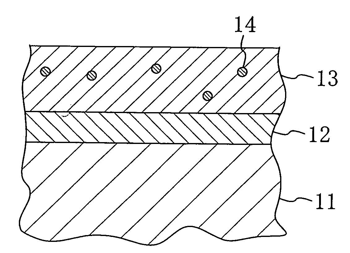
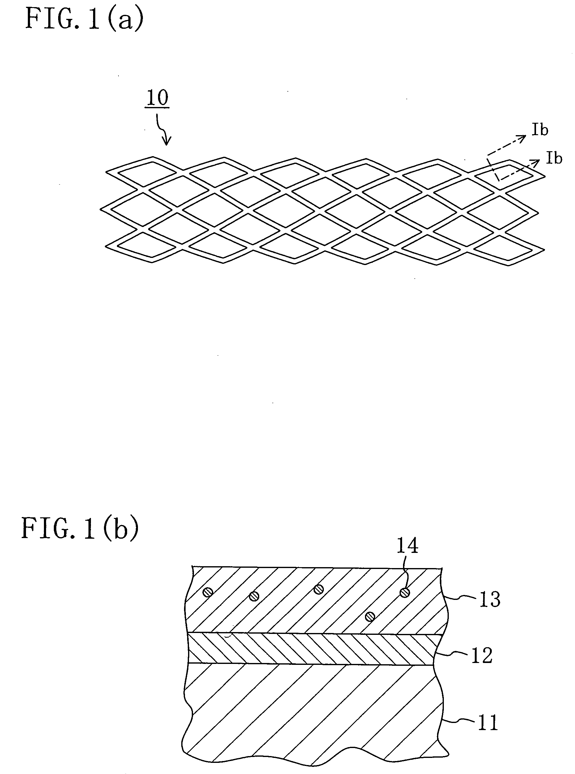
[0105]The stent of the present invention will now be described in detail by describing a specific example. In this example, a Co—Cr alloy stent having a length of 19 mm, a diameter of 1.5 mm and a cell thickness of 75 μm was used as the stent body 11.

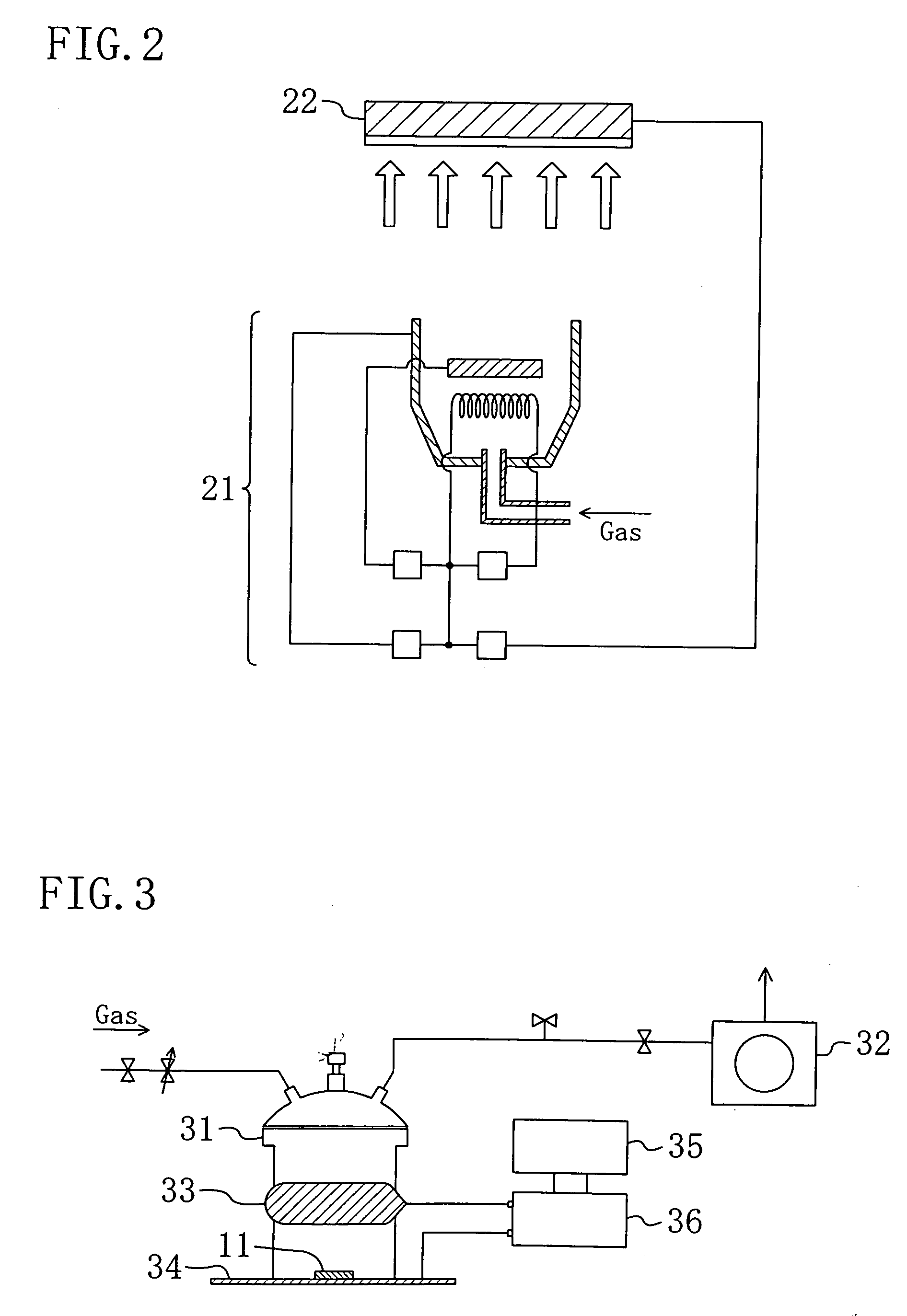
[0106]FIG. 2 schematically shows an ionization evaporation system used in this example, and this is a general ionization evaporation system in which a DLC film is solidified and deposited on a target 22 by colliding, against the target 22 biased to a negative voltage, plasma generated by introducing Ar and benzene (C6H6) gases corresponding to ion sources into a DC arc discharge plasma generator 21 provided within a vacuum chamber.

[0107]A stent body 11 was set within the chamber of the ionization evaporation system of FIG. 2, and bombardment cleaning, in which Ar ions are produced by discharging after introducing an argon gas (Ar) into the chamber so as to attain a pressure of 10−1 Pa through 10−3 Pa (10−3 Torr through 10−5 Torr) and th...


PUM

PropertyMeasurementUnit
thicknessaaaaaaaaaa
thicknessaaaaaaaaaa
thicknessaaaaaaaaaa

Abstract

A stent includes a tubular stent body 11, a diamond-like carbon film 12 formed on the surface of the stent body 11 and having an activated surface, and a polymer layer 13 immobilized on the surface of the diamond-like carbon film. The polymer layer 13 contains a drug 14 having an effect to prevent restenosis, and the drug 14 is gradually released from the polymer layer 13.

Description

TECHNICAL FIELD[0001]The present invention relates to a stent and a method for fabricating the same, and more particularly, it relates to a drug release stent and a method for fabricating the same.BACKGROUND ART[0002]In accordance with recent westernization in the lifestyle, ischemic heart diseases (including angina pectoris and cardiac infarction) are rapidly increasing in Japan. An ischemic heart disease is caused principally when coronary thrombosis or coronary twitch is caused additionally to an arteriosclerotic disease of a thick coronary artery extending on the heart surface.[0003]As a treatment method for angiostenosis, angioplasty (PTA, PTCA or the like) in which a small balloon is expanded within a blood vessel for the treatment is widely employed as a minimally invasive treatment. In employing this treatment method, however, stenosis (restenosis) is repeatedly caused in high probability. As a method for reducing the ratio of the restenosis, a stent placement technique is b...

Claims


Application Information

Patent Timeline
Patent Type & Authority Applications(United States)
IPC IPC(8): A61F2/06
CPCA61F2/91A61F2250/0067A61L31/084A61L31/10A61L31/16A61L33/025A61L2300/416A61L2300/606A61L2420/08
Inventor NAKATANI, TATSUYUKIOKAMOTO, KEISHIYAMASHITA, SHUZOKOMURA, IKUOMORI, KOJI
Owner TOYO ADVANCED TECH CO LTD
Why Eureka
Try Eureka