Radial Anisotropic Magnet Manufacturing Method, Permanent Magnet Motor Using Radial Anisotropic Magnet, and Iron Core-Equipped Permanent Magnet Motor

a technology of radial anisotropic magnets and manufacturing methods, which is applied in the direction of magnetic circuit rotating parts, magnetic circuit shapes/forms/construction, magnetic bodies, etc., can solve the problems of large resource balance of sm or co, difficult to apply pressureless sintering thereto, and not widely used as industrial materials. , to achieve the effect of increasing output, reducing size, and tranquility and controllability

Active Publication Date: 2009-01-08
PANASONIC CORP
View PDF4 Cites 20 Cited by
  • Summary
  • Abstract
  • Description
  • Claims
  • Application Information

AI Technical Summary

Benefits of technology

[0054]With the above-described configuration, in terms of the deformation with the viscous flow or the extension flow of the element of the resin composite, the radial anisotropic magnet is manufactured which has a density of 5.8 Mg / m3 or more and a maximum energy product (BH)max of 140 KJ / m3 or more. Accordingly, in a permanent magnet motor provided with an even number of the radial anisotropic magnets, particularly, in an iron core-equipped permanent magnet motor, it is possible to realize a decrease in size and an increase in output as well as tranquility and controllability of a permanent magnet motor mounted with an isotropic Nd2Fe14B bond magnet having (BH)max of approximately 80 KJ / m3 or so.
[0055]In the invention, there is provided the radial anisotropic magnet manufacturing method of fixing the magnet powder in a net shape so as to maintain the C-axis angle with respect to the tangential line and for performing the deformation with the flow so as to have the predetermined circular arc shape or the predetermined annular shape. It is possible to improve the shape compatibility of the magnet by improving the deformability with the extension flow or the viscous flow of the linear polymer. When a density of the magnet according to the invention is 5.8 Mg / m3 or more and a maximum energy product (BH)max thereof is 140 KJ / m3 or more, it is possible to further realize a decrease in size and an increase in output of the general motor applied with the isotropic Nd2Fe14B bond magnet having a density of 6 Mg / m3 and a maximum energy product (BH)max of approximately 80 KJ / m3 or more.
[0056]Meanwhile, regarding a bad influence with respect to tranquility and controllability of the radial anisotropic magnet motor, it is possible to control the C-axis angle with respect to the tangential direction at an arbitrary position and an arbitrary angle without separating the magnetic pole into segments.

Problems solved by technology

A basic power fixing means in powder metallurgy is pressureless sintering, but since the ribbon needs to maintain a magnetic characteristic based on a metastable state, it is difficult to apply the pressureless sintering thereto.
However, Sm or Co has a large problem of a resource balance, and thus is not widely used as an industrial material.
However, even when an ingot of Nd2Fe14B-based alloy or a sintered magnet is milled, the HCJ is small.
However, the cubic magnet is not suitable for a general permanent magnet motor.
Since it is difficult to generate a homogeneous radial magnetic field, a problem arises in that productivity is lower than that of the isotropic bond magnet.
The cogging torque prevents smooth rotation of the motor to make the cause impairing tranquility or controllability of the motor.
However, when the magnetic pole is separated into segments, since assembling precision largely influences the cogging torque, and a limitation in an actual shape or a configuration and complexity are overlapped, its production is difficult.
However, when a thickness of the magnet is, for example, 1.5 mm, since it is difficult to anisotropically stretch the perpendicular anisotropic thin-film magnet, there is a limitation in the thickness of the magnet in a deformation in which the magnetic characteristic is maintained.
However, when the magnetic pole is separated into segments, assembling precision critically influences the cogging torque.
The limitation in the actual shape or the configuration and complexity are overlapped, which is difficult to be carried out in an industrial field.

Method used


Image

  • Radial Anisotropic Magnet Manufacturing Method, Permanent Magnet Motor Using Radial Anisotropic Magnet, and Iron Core-Equipped Permanent Magnet Motor
  • Radial Anisotropic Magnet Manufacturing Method, Permanent Magnet Motor Using Radial Anisotropic Magnet, and Iron Core-Equipped Permanent Magnet Motor
  • Radial Anisotropic Magnet Manufacturing Method, Permanent Magnet Motor Using Radial Anisotropic Magnet, and Iron Core-Equipped Permanent Magnet Motor

Examples


example 1

[0099]A manufacturing method according to the invention will be described in more detail in terms of an example. However, the invention is not limited to this example.

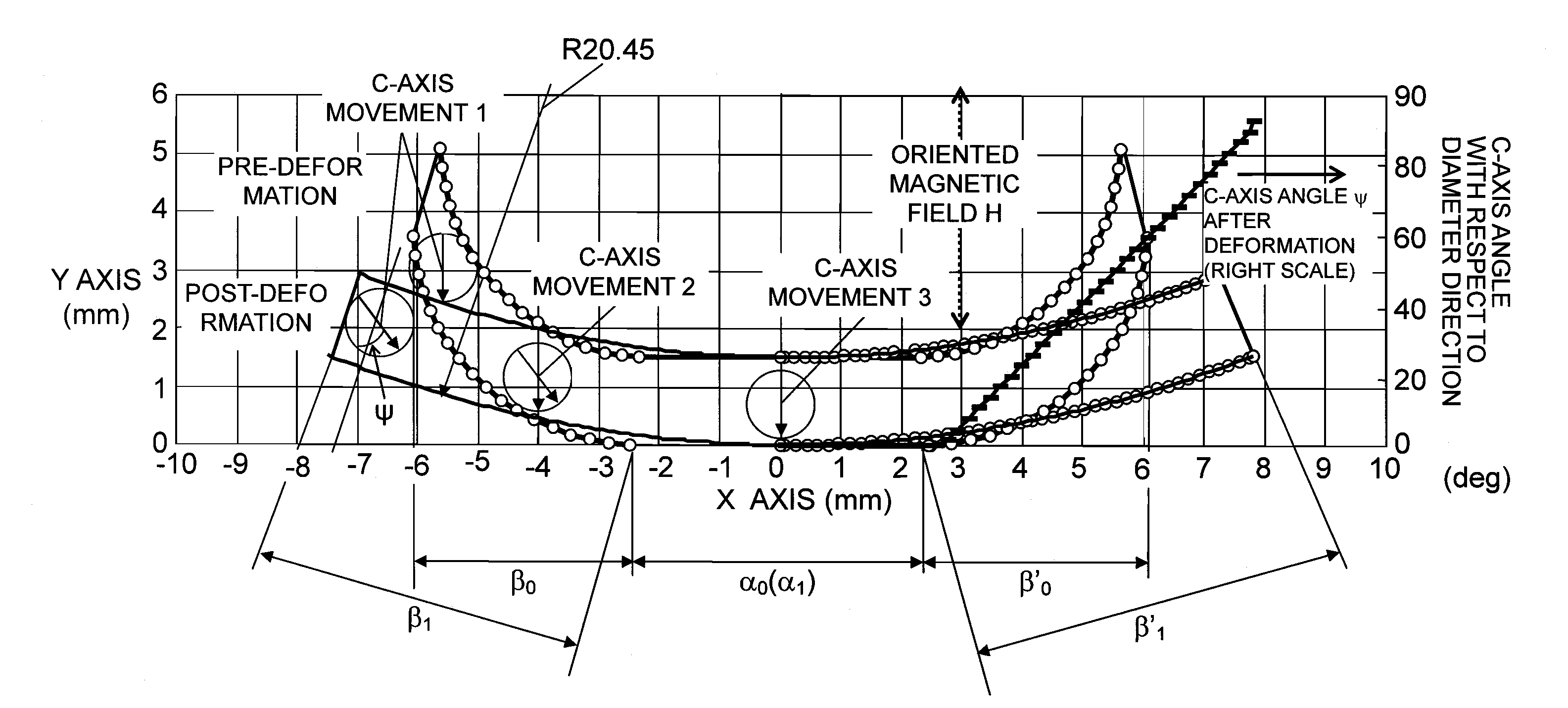
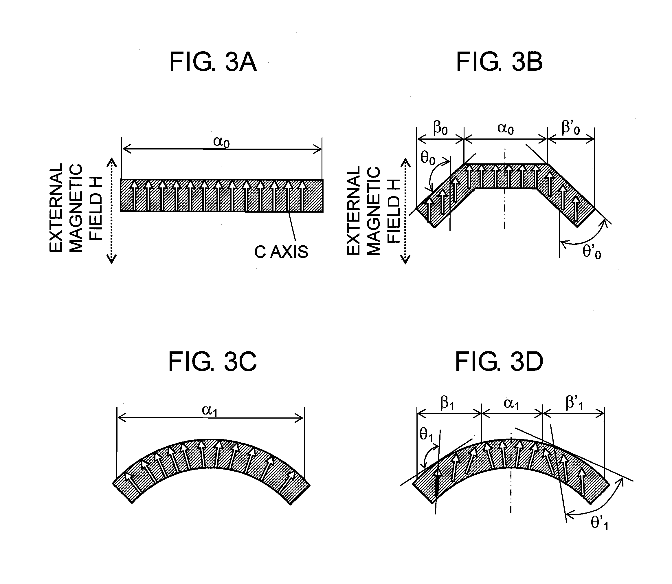
[0100]Radial Anisotropic Magnet Having C-Axis Angle of 90 Degree With Respect to Tangential Line

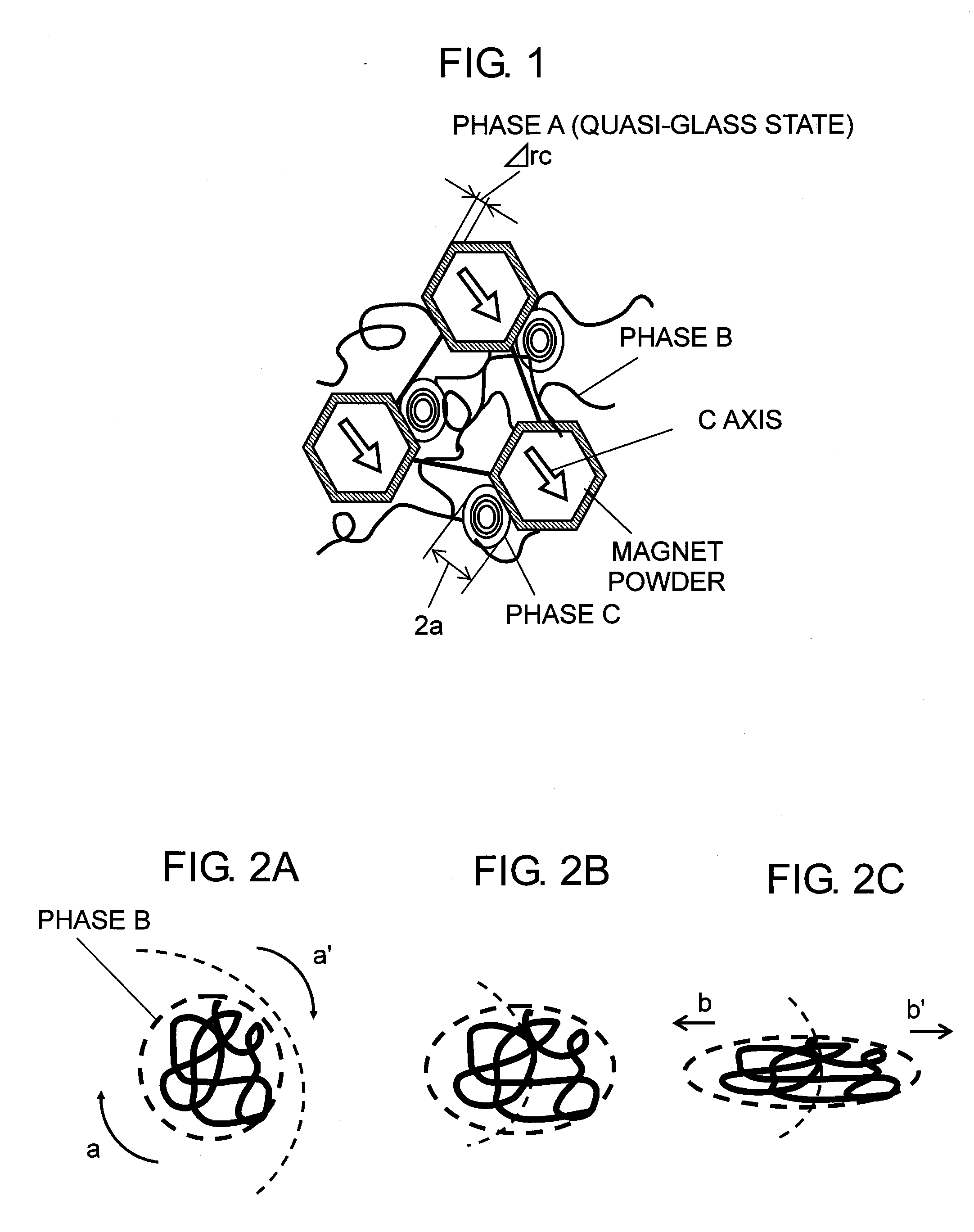
[0101]As magnet powder, anisotropic Sm2Fe17N3 having a particle diameter in a range of 3 to 5 μm and anisotropic Nd2Fe14B having a particle diameter in a range of 38 to 150 μm are used. In coupling agents, novolac-type epoxy having an epoxy equivalent in a range of 205 to 220 g / eq and a melting point in a range of 70 to 76° C. is used as oligomer as a main element of the magnet powder stationary phase A. The phase B is, for example, a linear polymer forming a cross-linking macromolecule in terms of a cross-linking reaction with the phase A, and for example, polyamide is used which has a melting point of 80° C. and a molecular mass in a range of 4,000 to 12,000. As the chemical contact of the phase C, 2-phenyl-4,5-dihydroxyme...


PUM

PropertyMeasurementUnit
magnetic anisotropic angleaaaaaaaaaa

Abstract

In order to improve tranquility and controllability of an iron core-equipped permanent magnet motor with an improvement of a maximum energy product (BH)max by improving a shape compatibility of a radial anisotropic magnet, there is provided a radial anisotropic magnet manufacturing method of fixing magnet powder in a net shape so as to maintain a magnetic anisotropic (C-axis) angle of a magnet with respect to a tangential line and for performing a deformation with a flow so as to have a predetermined circular arc shape or a predetermined annular shape. Particularly, by performing a deformation with a viscous flow or an extension flow, a deformability of the magnet is improved, and thus a shape compatibility with respect to a thickness is improved. AC-axis angle θ with respect to a tangential direction is controlled at an arbitrary position and an arbitrary angle so as to reduce cogging torque without separating a magnetic pole into segments.

Description

TECHNICAL FIELD[0001]The present invention relates to a radial anisotropic magnet manufacturing method including a deformation process. More specifically, the present invention relates to a method of manufacturing a magnet suitable for a decrease in size or an increase in output of a permanent magnet motor, and particularly suitable for a reduction of cogging torque accompanied by a rotation of an iron core-equipped permanent-type motor.BACKGROUND ART[0002]A type of magnet materials such as Nd2Fe14B, αFe / Nd2Fe14B, and Fe3B / Nd2Fe14B obtained by a melt span is limited to a thin band such as a ribbon or flake-shape powder obtained by milling the same. For this reason, in order to obtain a bulk-shape permanent magnet which is used in general, a technique is necessary which changes a type of material, that is, fixes the ribbon or the powder to a predetermined bulk in a certain manner. A basic power fixing means in powder metallurgy is pressureless sintering, but since the ribbon needs to...

Claims


Application Information

Patent Timeline
Patent Type & Authority Applications(United States)
IPC IPC(8): H01F7/02H02K21/12
CPCH01F1/0578H01F1/059Y10T29/49076H01F41/028H02K1/27H01F1/083
Inventor YAMASHITA, FUMITOSHIMURAKAMI, HIROSHIKAWAMURA, KIYOMI
Owner PANASONIC CORP
Why Eureka
Try Eureka