Hydrogen Production Apparatus, Fuel Cell System and Operation Method Thereof

a fuel cell and hydrogen production technology, applied in emergency supply, electrochemical generators, carburetor gases, etc., can solve the problems of requiring space to store nitrogen, requiring time and effort to supply and manage nitrogen, and still purging, so as to reliably suppress catalyst degradation and suppress catalyst degradation.

Inactive Publication Date: 2009-01-08
JX NIPPON OIL & ENERGY CORP
View PDF9 Cites 25 Cited by
  • Summary
  • Abstract
  • Description
  • Claims
  • Application Information

AI Technical Summary

Benefits of technology

[0024]According to the present invention, there is provided a hydrogen production apparatus which can more reliably suppress catalyst degradation due to oxidation in the hydrogen production apparatus even when start-ups and shutdowns are repeated without carrying out a purge operation upon shutting down the hydrogen production apparatus.
[00

Problems solved by technology

However, space is required to store nitrogen, and it takes time and effort to supply and manage nitrogen.
That is, purging is still carried out, and the shutdown operation cannot

Method used


Image

  • Hydrogen Production Apparatus, Fuel Cell System and Operation Method Thereof
  • Hydrogen Production Apparatus, Fuel Cell System and Operation Method Thereof
  • Hydrogen Production Apparatus, Fuel Cell System and Operation Method Thereof

Examples


first embodiment

[First Embodiment of the Fuel Cell System]

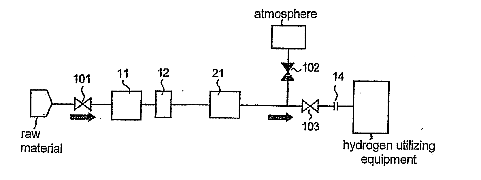
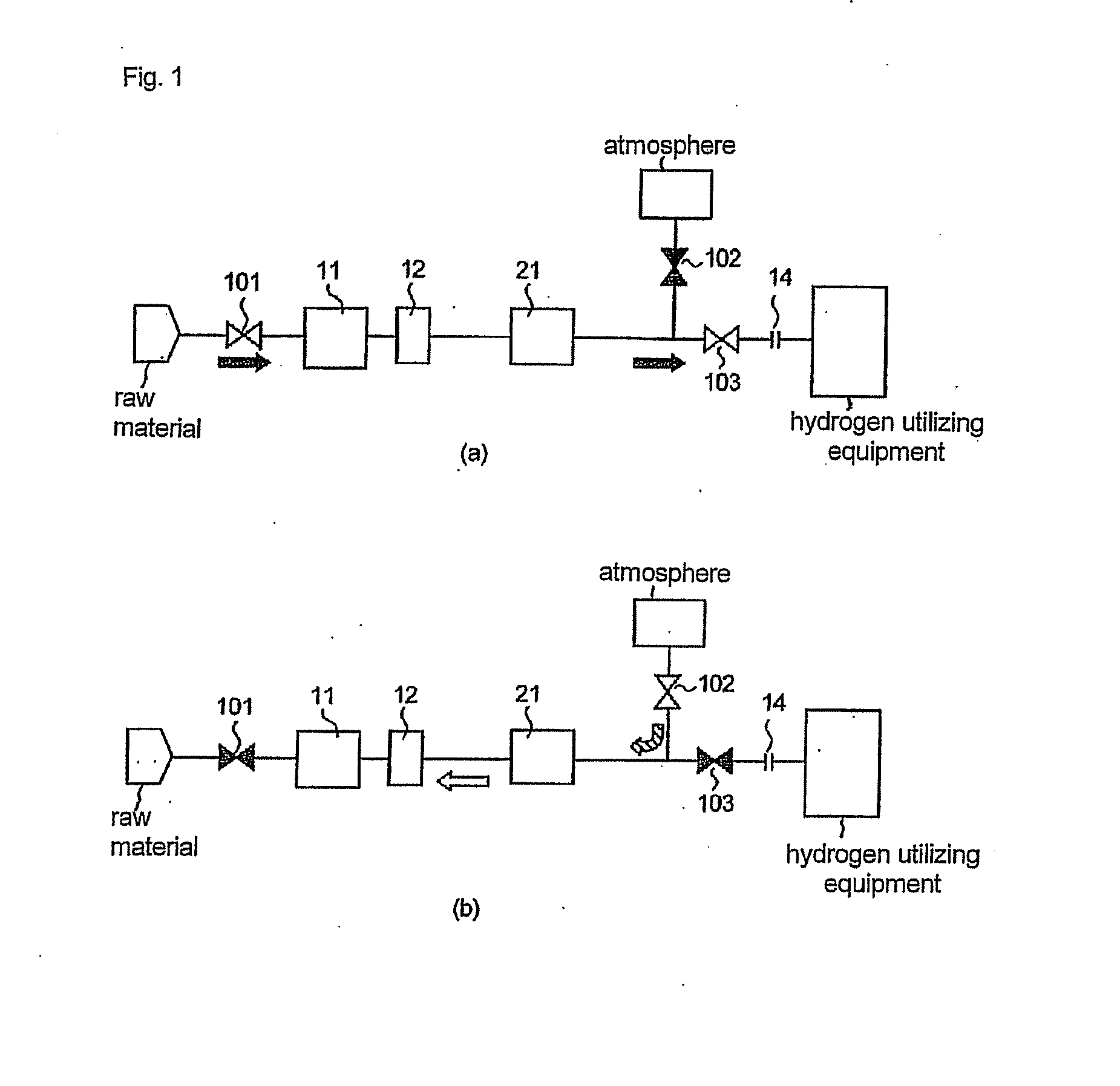
[0121]FIG. 4 is a series of flow diagrams illustrating the outline of an embodiment of the fuel cell system according to the present invention. This embodiment has a basic configuration which combines the hydrogen production apparatus 100 illustrated in FIG. 1 and a fuel cell 2, and is suitable for a polymer electrolyte fuel cell. As illustrated in FIG. 2, the selective oxidation reactor has a structure in which a selective oxidation catalyst bed and an oxygen absorbent bed are stacked in the interior, and the oxygen absorbent bed is arranged on the downstream side.

[0122]As illustrated in FIG. 4(a), during operation of the fuel cell system, the valve 102 is closed, and the valve 103 is open. The hydrogen-containing gas produced by the hydrogen production apparatus 100 is supplied to an anode chamber 2a of the fuel cell 2, and is used to generate power. Since the anode off gas discharged from the anode chamber contains combustible substances,...

second embodiment

[Second Embodiment of the Fuel Cell System]

[0131]FIG. 5 illustrates another embodiment of the fuel cell system according to the present invention. As illustrated in FIG. 2, the selective oxidation reactor has a structure in which a selective oxidation catalyst bed and an oxygen absorbent bed are stacked in the interior, and the oxygen absorbent bed is arranged on the downstream side. In this embodiment, in addition to removing the oxygen with the oxygen absorbent, oxygen is also removed by the fuel cell. In the embodiment of FIG. 4, the line between the selective oxidation reactor 21 and the valve 103 is branched, and the reformer and the like can be opened to the atmosphere via the valve 102. However, in the embodiment illustrated in FIG. 5, the line between the selective oxidation reactor 21 and the valve 103 is branched, and the reformer and the like can be opened to the atmosphere via the cathode chamber 2c of the fuel cell and the air pressure increasing means 4 in addition to ...

example 1

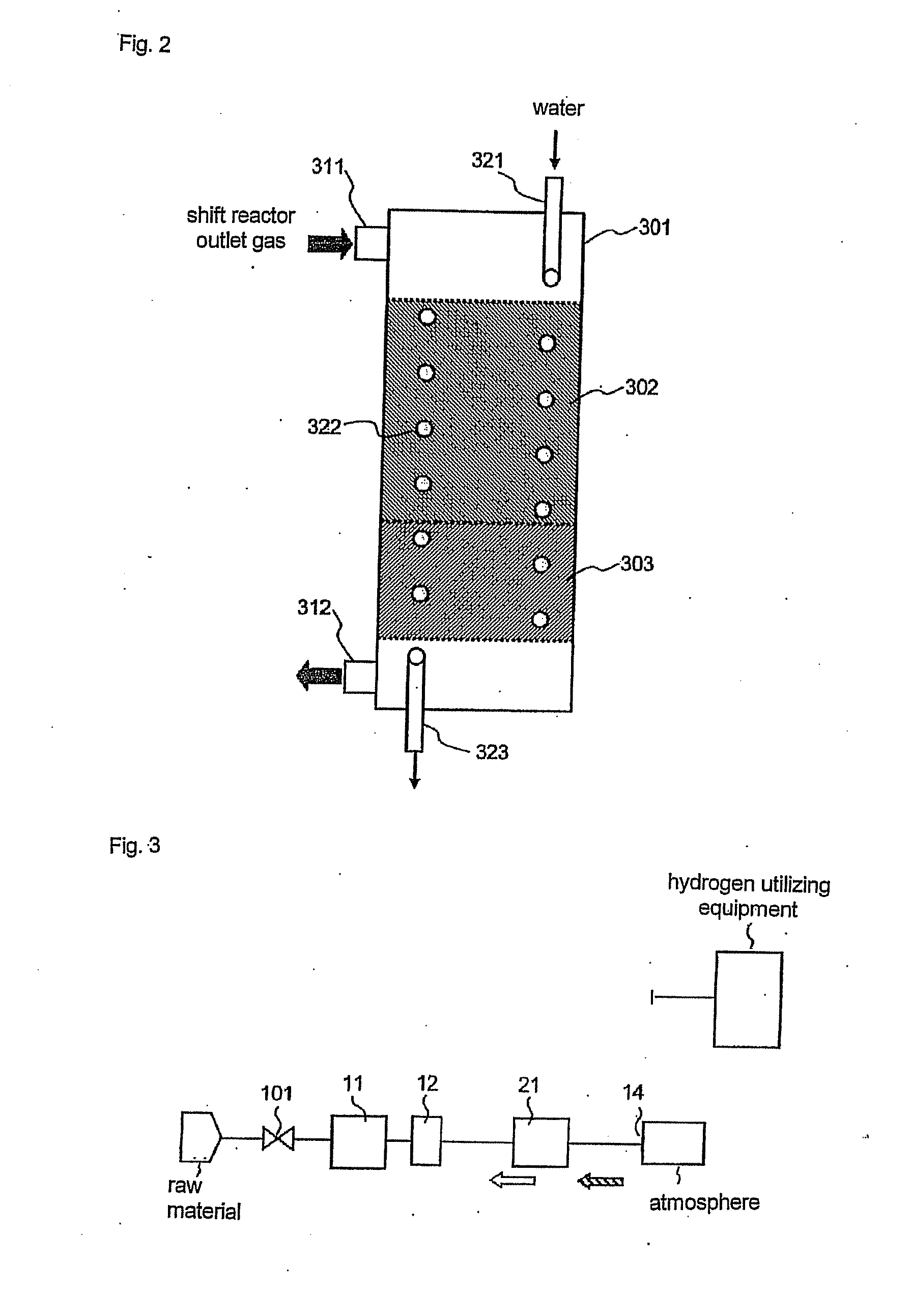
[0142]A hydrogen production apparatus having the configuration illustrated in FIG. 1 was prepared. A copper-zinc catalyst which had been reduced by hydrogen was filled in the shift reactor 12 as a shift catalyst. A reactor having the structure illustrated in FIG. 2 was used for the selective oxidation reactor 21. An oxygen absorbent bed 303 filled with 200 mL (bulk volume) of an oxygen absorbent containing 5 mass % of Ru, 20 mass % of Y2O3, and a balance of alumina was formed in the selective oxidation reactor as a downstream side packed bed in a vessel 301 which is to be packed with the selective oxidation catalyst. The oxygen absorption capacity of this oxygen absorbent was 5.0 (mL-O2 / mL-catalyst).

[0143]A selective oxidation catalyst bed 302 filled with 400 mL (bulk volume) of a selective oxidation catalyst supporting 0.35 mass % of Ru as metal mass on an alumina support was formed upstream of the oxygen absorbent bed.

[0144]In the vessel 301, a coil-shaped cooling water pipe (nomi...


PUM


Abstract

There are provided a hydrogen production apparatus, a fuel cell system and operation method thereof, which can more reliably suppress degradation due to oxidation of a catalyst in a hydrogen production apparatus even when start-ups and shutdowns are repeated without a purge operation during the shutdowns. The hydrogen production apparatus includes a reforming part, a shift reaction part, and a selective oxidation reaction part having a selective oxidation catalyst bed packed with a selective oxidation catalyst, wherein the hydrogen production apparatus has an oxygen absorbent bed packed with an oxygen absorbent capable of absorbing oxygen and capable of being regenerated by a reducing gas, and the oxygen absorbent bed and the selective oxidation catalyst bed are stacked with the oxygen absorbent bed on the downstream side, and the hydrogen production apparatus has means for opening the downstream of the oxygen absorbent bed to the atmosphere. The fuel cell system has this hydrogen production apparatus. The operation method of this fuel cell system includes opening the downstream of the oxygen absorbent bed to the atmosphere upon shutdown of the fuel cell system, and regenerating the oxygen absorbent using a hydrogen-containing gas during hydrogen production by the hydrogen production apparatus.

Description

TECHNICAL FIELD[0001]The present invention relates to a hydrogen production apparatus for producing hydrogen from a raw material for hydrogen production such as city gas, liquefied petroleum gas (LPG), kerosene and the like, and a fuel cell system which uses a hydrogen-containing gas produced by this hydrogen production apparatus as fuel.BACKGROUND ART[0002]The development of fuel cells is intensifying, since it is said that fuel cells are a power generation system having good energy utilization efficiency. Among fuel cells, polymer electrolyte fuel cells are especially drawing attention due to their high power density and ease of handling.[0003]For a fuel cell, which generates power through an electrochemical reaction between hydrogen and oxygen, it is essential to establish hydrogen supply means. One method for doing this is to produce hydrogen by reforming a raw material for hydrogen production such as a hydrocarbon fuel. From the viewpoint that supply systems of hydrocarbon fuel...

Claims


Application Information

Patent Timeline
IPC IPC(8): H01M8/22
CPCC01B3/38Y02B90/14C01B3/48C01B13/0262C01B2203/0233C01B2203/0261C01B2203/0283C01B2203/044C01B2203/047C01B2203/066C01B2203/1047C01B2203/1076C01B2203/127C01B2203/1604C01B2203/1609C01B2210/0046H01M8/04223H01M8/0618H01M8/0631H01M8/0662H01M8/0668Y02E60/50C01B3/386H01M8/04228H01M8/04303Y02B90/10H01M8/04H01M8/06H01M8/0267H01M8/043
Inventor SATO, YASUSHIGOTO, AKIRASAMURA, KENFUJU, AKIRAKADOWAKI, MASATAKA
Owner JX NIPPON OIL & ENERGY CORP
Why Eureka
Try Eureka