Eureka AIR delivers breakthrough ideas for toughest innovation challenges, trusted by R&D personnel around the world.

Electrophysiological sensor, weak electrical signal conditioning circuit and method for controlling said circuit

Inactive Publication Date: 2009-01-22
STARLAB BARCELONA SL
View PDF8 Cites 52 Cited by
  • Summary
  • Abstract
  • Description
  • Claims
  • Application Information

AI Technical Summary

Benefits of technology

[0030]More specifically, the proposed electrophysiological sensor is of the type comprising a plurality of conducting nanostructures which can transmit a weak electrical signal captured from the skin or from another part of an organic tissue to a transmitter means formed for example by an electrical connector which continues in a conductor or wiring and is characterized by integrating a structure of multiple carbon nanotubes fixed to a suitable conducting support substrate, said nanotubes emerging from said substrate in the form of substantially rigid and filiform elements, like needles. The fixing does not require a polymer layer for adhering the nanotubes. These rigid and filiform nanostructures are thus chemically connected at one end to said conducting substrate linked to an electrical connector and are operable to at least partially penetrate said organic tissue or skin at their free end like needles, without needing any intermediate gel or interface, i.e., the electrophysiological sensor operates in dry conditions on the skin which must not have been previously subjected to a previous preparation treatment. The contact and partial penetration of the nanotubes in the Stratum Corneum (outer layer of the epidermis with a thickness of 10 to 20 μm and forming a resistive medium) allow a stable electrical contact with low impedance and noise.
[0081]The interferences of the biopotential signals are considerably reduced, and the offsets experienced by such signals are compensated by means of implementing said preferred embodiment, using the high performance of both the electrophysiological sensor proposed by the first aspect, and the conditioning circuit proposed by the second aspect.

Problems solved by technology

The need to apply an interface layer between the electrode or sensor and the skin or another organic tissue involves some drawbacks: it is necessary to invest a long time preparing the skin and the device (in the order of a few minutes) for each intervention.
The gel-skin interface is not a stable interface, which adds noise (electrode-skin, electrode-polymer or gel, gel-skin) to the measurements taken, disrupting its reliability.
The conductive gel can further undergo modifications such as drying out (at least to a certain extent) during the process and therefore adding even more noise to the involved information.
The main problem in biopotential measurements are the interferences, including the dominant noise of the line frequency of 50 or 60 Hz.
The slight imbalances in the lengths and the contacts of the electrodes cause the common-mode signal to be offset in direct current, which forms the main limitation of the differential amplifier of the instrumentation amplifier.
In all the mentioned system proposals including DRL circuits there is an electrical connection between the latter and the circuit conditioning the signals coming from the electrodes, since the voltage applied to the DRL electrode corresponds to the common-mode voltage detected in the differential amplifiers connected to each electrode, which makes the fluctuations in the electrical signals provided by the electrodes and the possible artifacts, or interfering signals, cause changes in the voltage to be applied to the DRL electrode, which results in the occurrence of a current injection in the patient through the DRL electrode-skin-tissue interface, altering the balance in the potentials of the half-cells.

Method used


Image

  • Electrophysiological sensor, weak electrical signal conditioning circuit and method for controlling said circuit
  • Electrophysiological sensor, weak electrical signal conditioning circuit and method for controlling said circuit
  • Electrophysiological sensor, weak electrical signal conditioning circuit and method for controlling said circuit

Examples


first embodiment

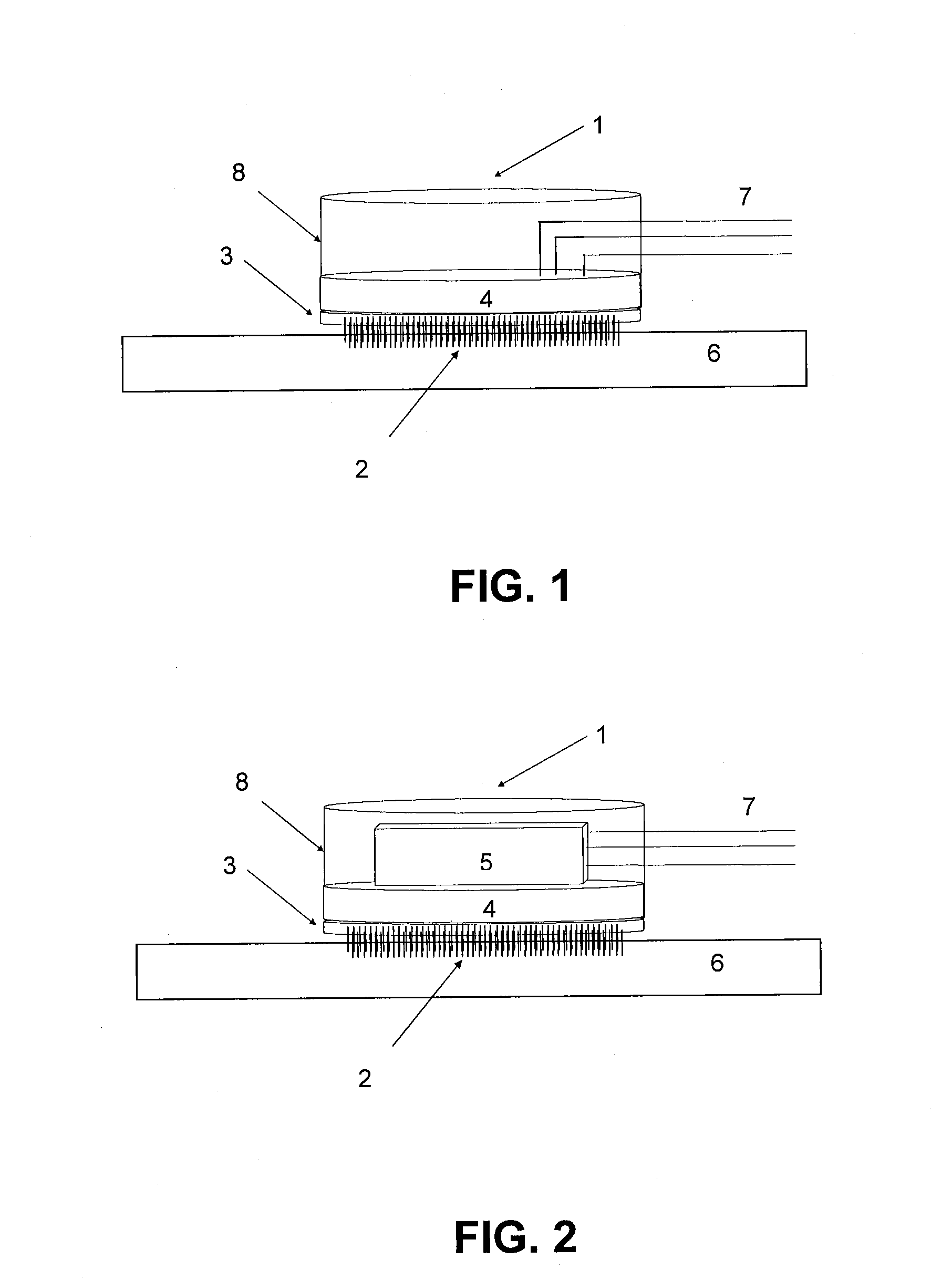
[0031]In a first embodiment the electrophysiological sensor of the invention comprises an envelopment casing housing said connector and which has associated to an outer wall the mentioned conducting substrate supporting the nanostructures.

[0032]According to a second preferred embodiment it has been provided that the sensor includes a local amplifier in association with said connector.

[0033]In an even more improved third version the sensor additionally includes a circuit for a treatment (pre-processing or processing) or at least partial adaptation of the weak electrical signals captured from the skin.

[0034]In an even more improved fourth version, the incorporation of an electronic circuit for transmitting the data captured by the sensor, by radiofrequency, to a remote management point has been provided.

[0035]The transmission and control of the electronic circuit associated to sensor is carried out wirelessly being able to couple, if necessary, other digital communication devices, as ...

second embodiment

[0084]FIG. 2 shows a second embodiment similar to the first in which an amplifier installed inside the cover of the assembly has been added to the sensor;

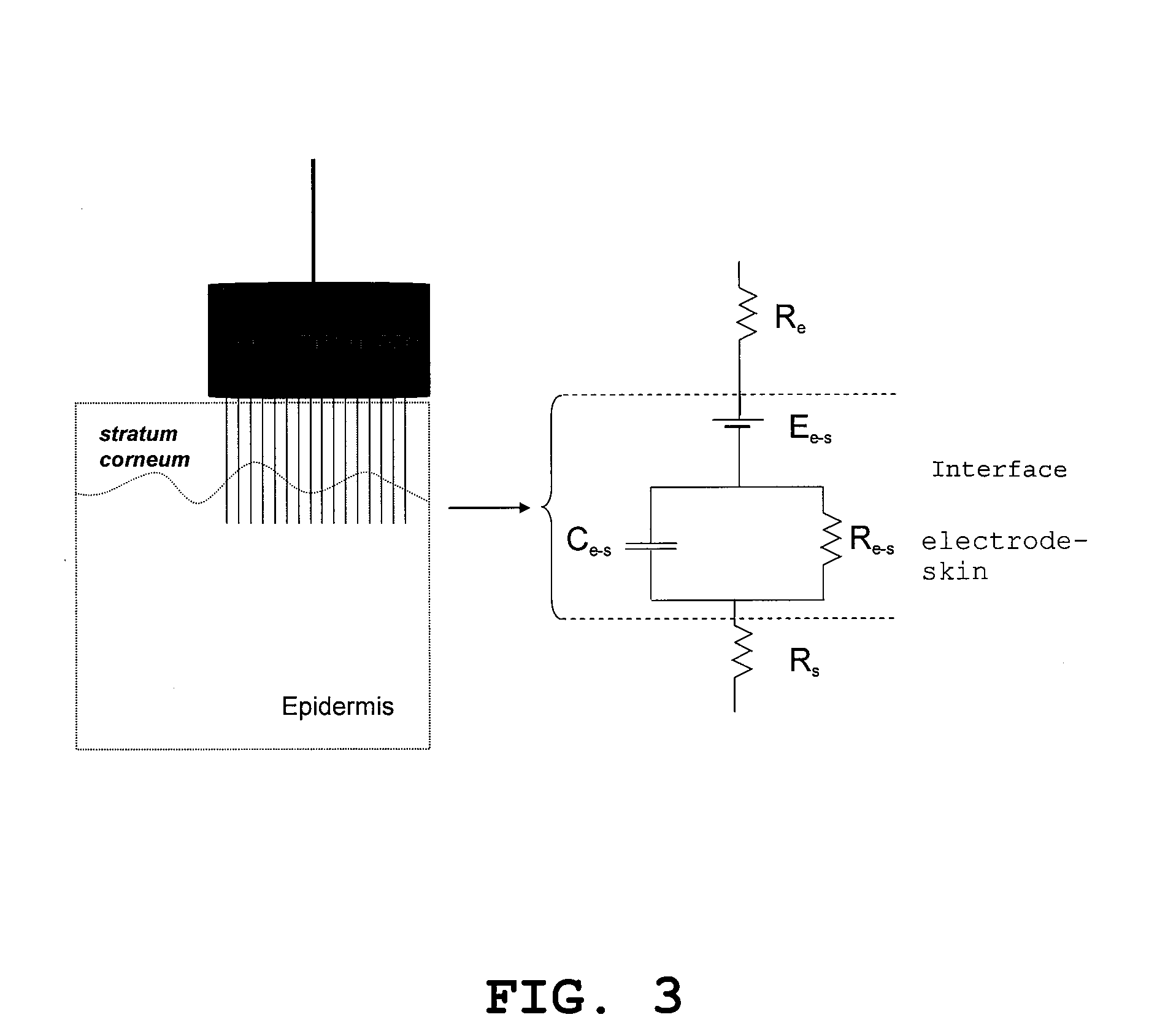
[0085]FIG. 3 shows an electrical diagram or equivalent circuit representative of the operation of the sensor described by the first aspect of the present invention, the resistance of the sensor, the properties of the interface and other variables being indicated in this depiction;

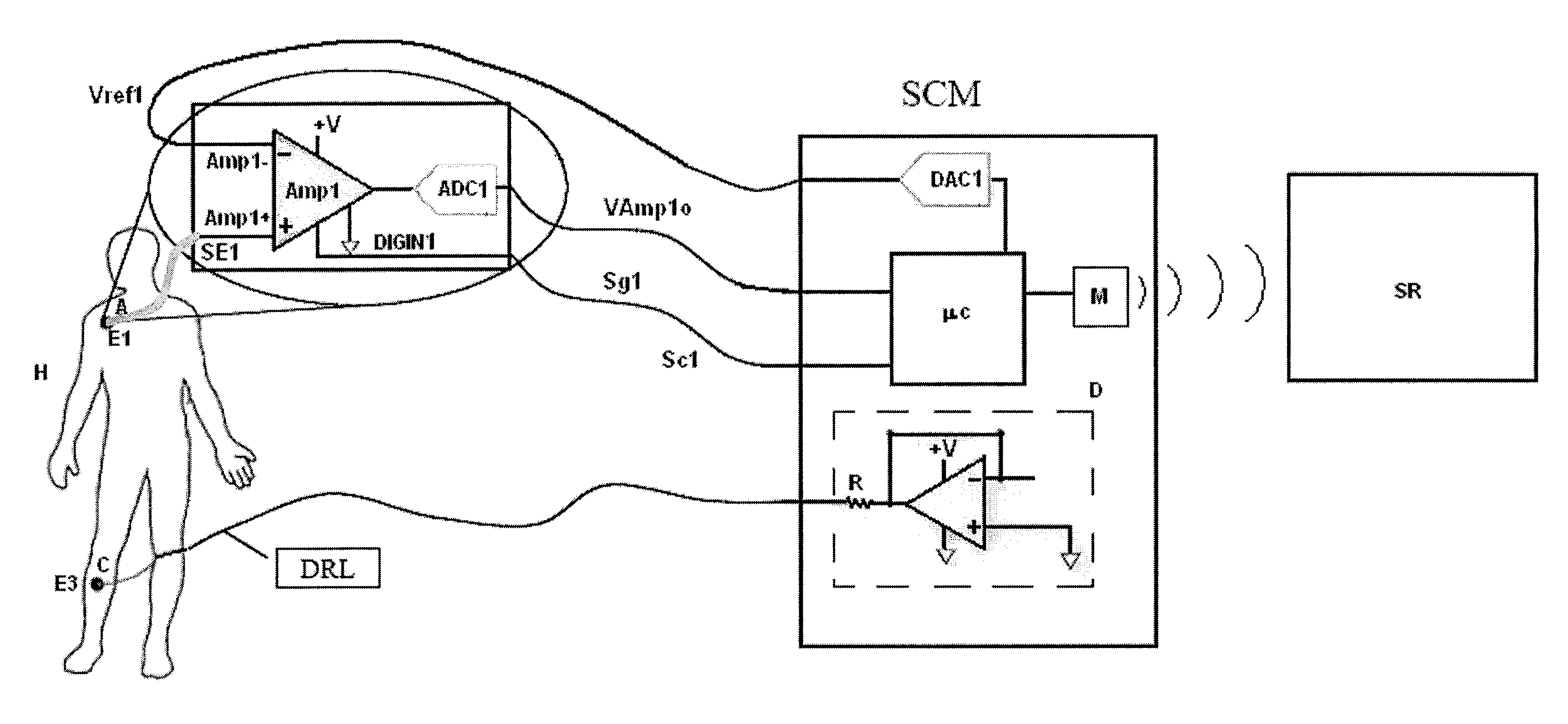
[0086]FIG. 4 is a schematic depiction of the conditioning circuit proposed by the second aspect of the invention applied to conditioning biopotential signals of a patient, specifically ECG signals, for an embodiment for which the signals come from a single receiver electrode;

[0087]FIG. 5 is a view similar to FIG. 4, but for an embodiment for which the conditioning circuit is applied to conditioning signals coming from two receiver electrodes,

[0088]FIG. 6 shows the method proposed by the third aspect of the invention, for an embodiment, by means of a flow c...


PUM


Abstract

An electrophysiological sensor, weak electrical signal conditioning circuit and method for controlling the circuit as provided. The sensor includes rigid filiform conducting nanostructures connected to a conducting substrate and operable to penetrate an organic tissue. The circuit includes an instrumentation amplifier with an input connected to a first electrode in contact with a first area of a medium, and a second input; a voltage generating device connected to an electrode in contact with a second area of the medium for applying a continuous reference signal to it; a compensator, electrically insulated from the device, for compensating the direct current offsets of a weak electrical signal received by the first electrode, generating a signal with a reference voltage with a value which can be modified by a control system, and supplying it to the second input. A method is also provided for controlling the circuit.

Description

FIELD OF THE INVENTION[0001]The present invention generally relates, in a first aspect, to an electrophysiological sensor, i.e., an electrode assembly for electrophysiological applications—and particularly to a sensor adapted for electrophysiological applications which do not require conducting substances acting as an interface between the sensor and the signal taking area.[0002]The invention likewise relates to an electrophysiological sensor operating in dry conditions particularly applicable to transmitting weak electrical signals (such as biological potential or biopotential signals) with low noise, through the skin, based on nanotechnology.[0003]The present invention also generally relates, in a second aspect, to a weak electrical signal, generally biological potential signal, conditioning circuit, and, in a third aspect, to a method for controlling such circuit, and particularly to a circuit and a method adapted for conditioning weak electrical signals coming from a medium, com...

Claims


Application Information

Patent Timeline
IPC IPC(8): A61B5/05
CPCA61B5/0408A61B5/0478A61B5/0492A61B5/7232A61B2562/0209A61B2562/046A61B5/685A61B2562/0215A61B5/25A61B5/291A61B5/296
Inventor RUFFINI, GIULIODUNNE, STEPHENFARRES, ESTEVE
Owner STARLAB BARCELONA SL
Why Eureka
Eureka Blog
Learn More