Magnetic resonance examination platform with independently moveable bed and antenna device

a magnetic resonance examination and independent moving technology, applied in the field of examination platforms, can solve the problems of increasing the electrical losses in the patient's body, the limited use possibilities of individual surface antennas, and the inability of single surface antennas to generate effective images, so as to reduce distance and increase the signal-noise ratio of acquired magnetic resonance signals.

Inactive Publication Date: 2009-01-29
SIEMENS HEALTHCARE GMBH
View PDF10 Cites 55 Cited by
  • Summary
  • Abstract
  • Description
  • Claims
  • Application Information

AI Technical Summary

Benefits of technology

[0034]In one embodiment of the inventive method, the local antenna device or local antenna device elements are moved in a plane perpendicular to the longitudinal axis of the patient bed before and/or during the acquisition of the image data such that the local antenna device or the local antenna device elements converge in the plane. This has the advantage that the signal-noise ratio of the acquired magnetic resonance signals increases due to the reduced distance.
[0035]In a preferred embodiment of the method according to the invention, the local antenna device is positioned in the a

Problems solved by technology

A disadvantage is that a single surface antenna is only able to generate an effective image within a specific spatial extent which lies on the order of the diameter of the conductor loops of the surface antenna.
The usage possibilities for such individual surface antennas are therefore very limited due to the limited observation range (field of view).
However, an increase of the electrical losses in the body of the patient and an associated increase in noise result from the enlargement of the conductor loop.
However, one problem with the use of multiple antenna elements is that the patient can perceive the coverage of body regions over a large area as objectionable, which in extreme cases sometimes leads to a termination of the examination.
Moreover, the application of additional sensors (such as electrocardiogram electrodes) is made more difficult given a coverage of the patient over a large area.
The high costs that arise due to the purchase of numerous antenna elements represents an additional disadvantage.
Moreover, the handling of the individual antenna elements of the multiple elements (i.e. the application and removal of the antenna elements) is time-consuming and therefore cost-intensive.
Moreover, the probability of an incorrect placement of the antenna elements on the body of the patient increases with the number of antenna elements, which can lead to an impairment of the image quality.
A further disadvantage of the su

Method used


Image

  • Magnetic resonance examination platform with independently moveable bed and antenna device
  • Magnetic resonance examination platform with independently moveable bed and antenna device
  • Magnetic resonance examination platform with independently moveable bed and antenna device

Examples


Embodiment Construction

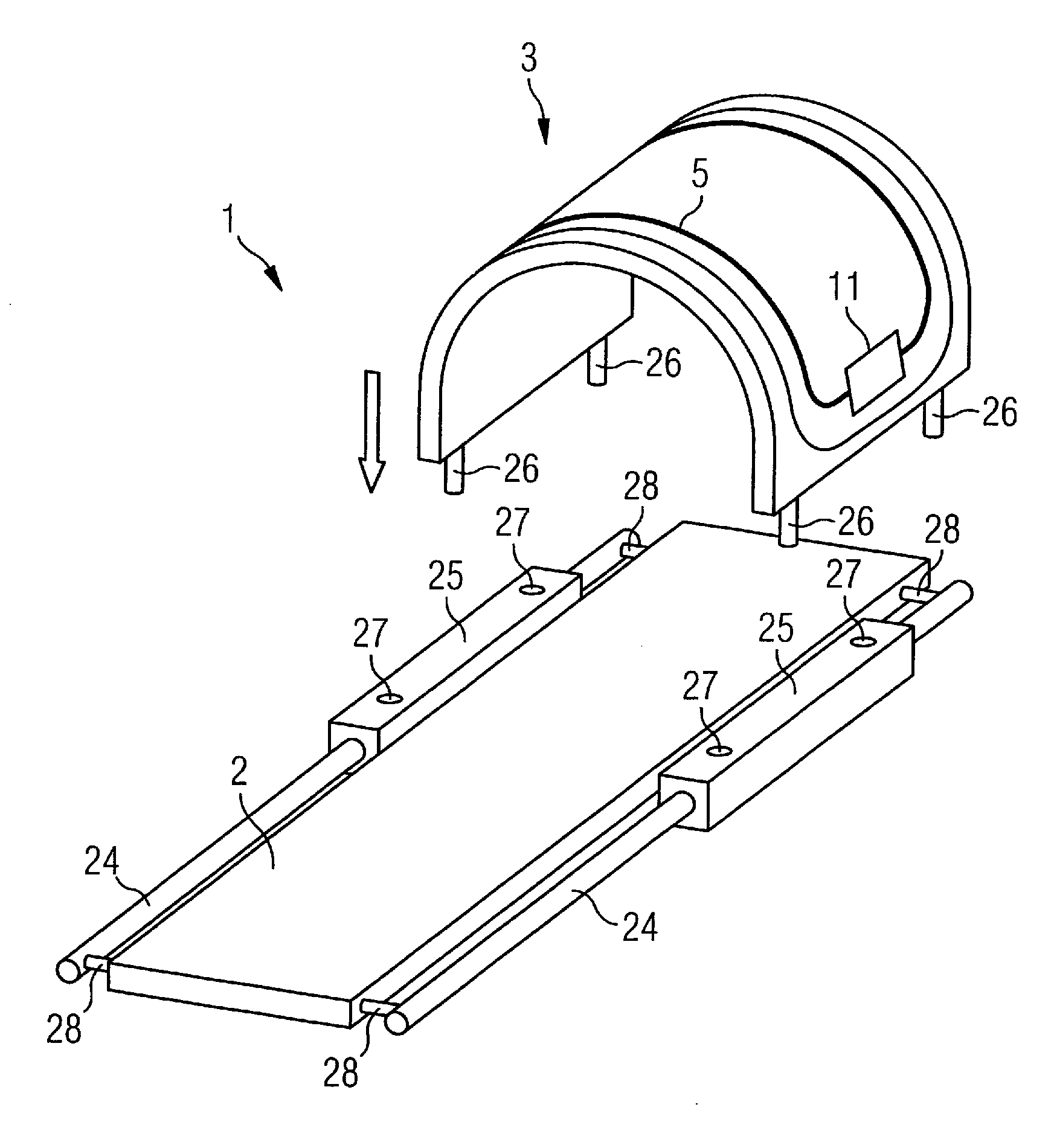
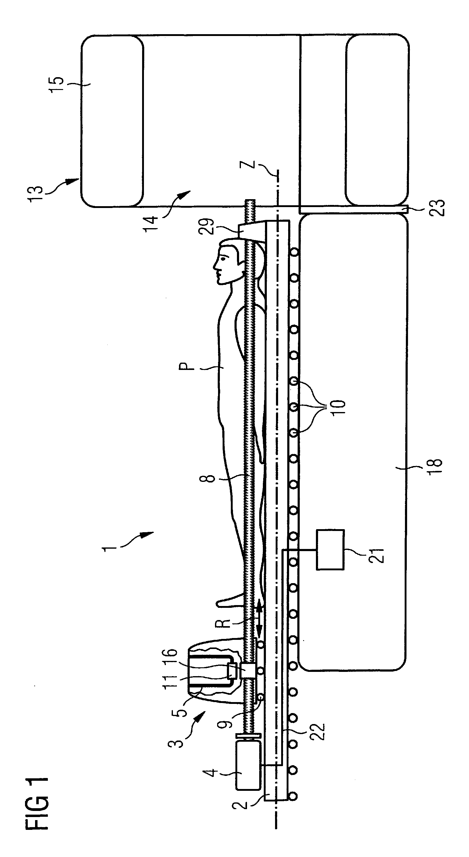
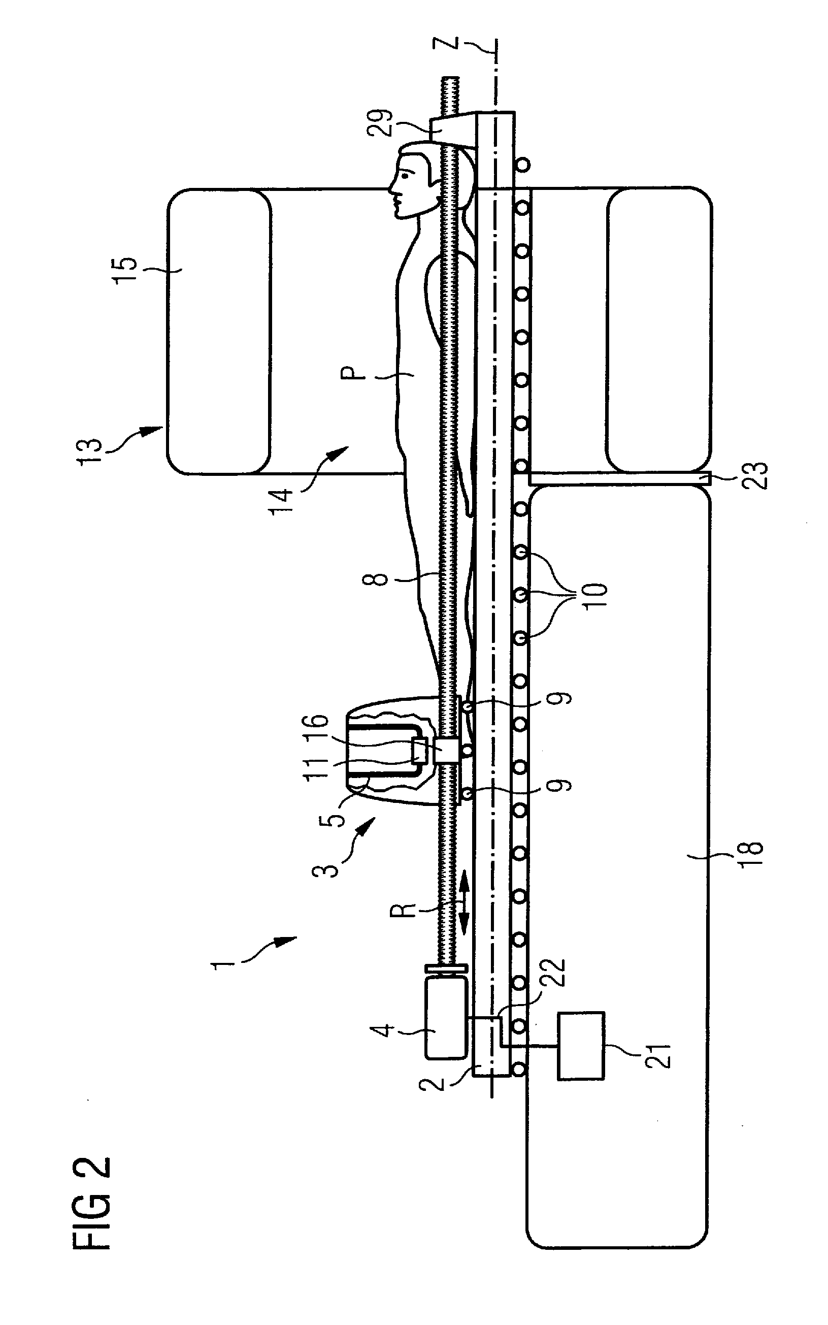
[0045]FIG. 1 shows a schematic side view of an embodiment of the examination platform 1 according to the invention, with a local antenna device 3 arranged above a patient bed 2 as well as a patient P and a magnetic resonance apparatus 13 in side view. The magnetic resonance apparatus 13 is coupled via an interface 23 with the examination platform 1 and has an acquisition space 14 that is surrounded by an annular or U-shaped (i.e. laterally open) tomography housing 15 in which are housed in a typical manner a whole-body radio-frequency coil, a basic field magnet, gradient coils, etc. For clarity, a further presentation of the technical details of a magnetic resonance apparatus 13 have not been included since these are known to those skilled in the art. The patient bed 2 can be moved along its longitudinal axis Z relative to a base 18 on rollers 10. The base 18 and the tomography housing 15 can also be fashioned as a combined housing. Other embodiments for a movable support of a patie...


PUM


Abstract

An examination platform for a magnetic resonance apparatus has a patient bed for supporting a patient, a local antenna device for acquisition of magnetic resonance signals, and a drive device arranged at the patient bed. The drive device is coupled with the local antenna device. The local antenna device thus can be moved parallel to the longitudinal axis of the patient bed independently of a movement of the patient bed. A magnetic resonance apparatus and a method for acquisition of image data of a patient employ such an examination platform.

Description

BACKGROUND OF THE INVENTION[0001]1. Field of the Invention[0002]The present invention concerns an examination platform for a magnetic resonance apparatus with a movable patient bed, a movable local antenna device for acquisition of magnetic resonance signals, and a drive for moving the bed. The invention also concerns a magnetic resonance apparatus with such an examination platform as well as a method for acquisition of image data of a patient with a magnetic resonance apparatus.[0003]2. Description of the Prior Art[0004]Medical technology imaging systems today assume an important role in the examination of patients. The depictions generated by the imaging systems of the internal organs and structures of the patients are used for diagnosis of pathological causes, for planning of operations, in the implementation of operations, as well as for preparation of therapeutic measures. Examples of such imaging systems are computed tomography systems, ultrasound systems, angiography devices,...

Claims


Application Information

Patent Timeline
IPC IPC(8): G01R33/34A61B5/055
CPCA61B5/0555A61B5/7203G01R33/56375G01R33/34084G01R33/3415G01R33/34007A61B5/055A61B5/704
Inventor DECKE, GUENTHERFISCHER, HUBERTUSSCHNELL, WILFRIED
Owner SIEMENS HEALTHCARE GMBH
Why Eureka
Try Eureka