Downhole Electric Driven Pump Unit

a technology of electric drive and pump unit, which is applied in the direction of fluid removal, positive displacement liquid engine, borehole/well accessories, etc., can solve the problems of low pump lift performance, short service life of flexible plane diaphragm, etc., to increase the pump's lift performance, avoid wear, and double the pump's capacity

Inactive Publication Date: 2009-02-12
PONOMAREV ANATOLY KONSTANTINOVICH +3
View PDF10 Cites 25 Cited by
  • Summary
  • Abstract
  • Description
  • Claims
  • Application Information

AI Technical Summary

Benefits of technology

[0007]The pump can be equipped with additional suction valves, which can be placed coaxially in the cylinder walls of the plunger working pump and oil expansion joint in one or multiple rows. Making the oil expansion joint with suction and pressure valves and connecting it to the chamber between the working pump pressure valve and the lift valves doubles the pump's capacity by pumping oil on the hydraulic motor piston's reciprocal stroke, avoids wear and tear on the working pump plunger seals (as they operate in oil and do not directly contact the pump medium), and increases the pump's lift performance. The pump end effector is a cylindrical diaphragm made of a flexible material such as rubber reinforced with glass fiber or Kevlar, which increases the membrane's durability. The plunger working pump end effector is a hermetic oil-filled chamber bounded by a cylindrical flexible diaphragm, within which the plunger moves reciprocally; this decreases the cyclical load on the diaphragm (as compared with the diaphragm pump indicated above) and thereby increases the plunger working pump's operating reliability. Another advantage of the proposed technical solution is that the pump lift performance and capacity can vary widely by changing the working pump plunger diameter.

Problems solved by technology

The known design has shortcomings of low efficiency, short service life for the flexible plane diaphragm due to high stroke frequency, low pump lift performance, inability to extract oil with low water cut due to the suction valves' poor carrying capacity.
The drawback of this design is wear and tear of the working pump plunger seals, which decreases the pump's capacity and lift performance.

Method used


Image

  • Downhole Electric Driven Pump Unit
  • Downhole Electric Driven Pump Unit
  • Downhole Electric Driven Pump Unit

Examples


Embodiment Construction

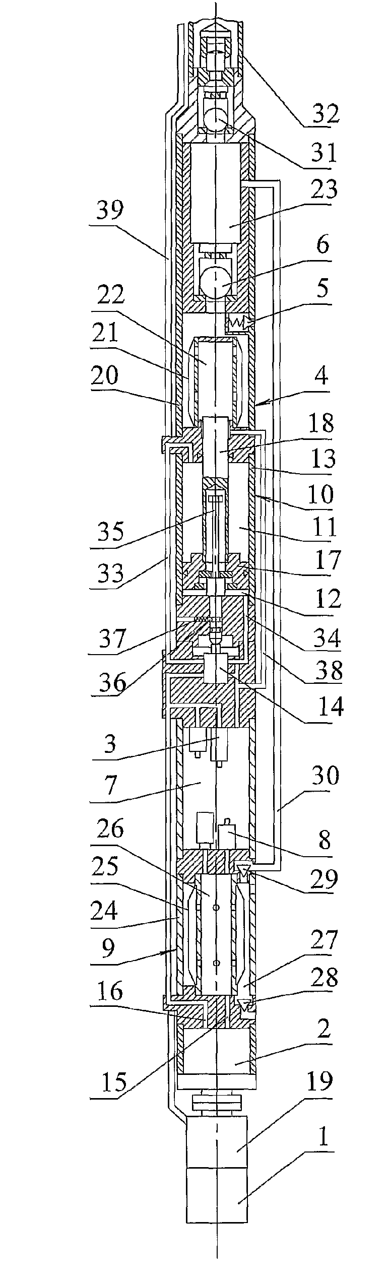
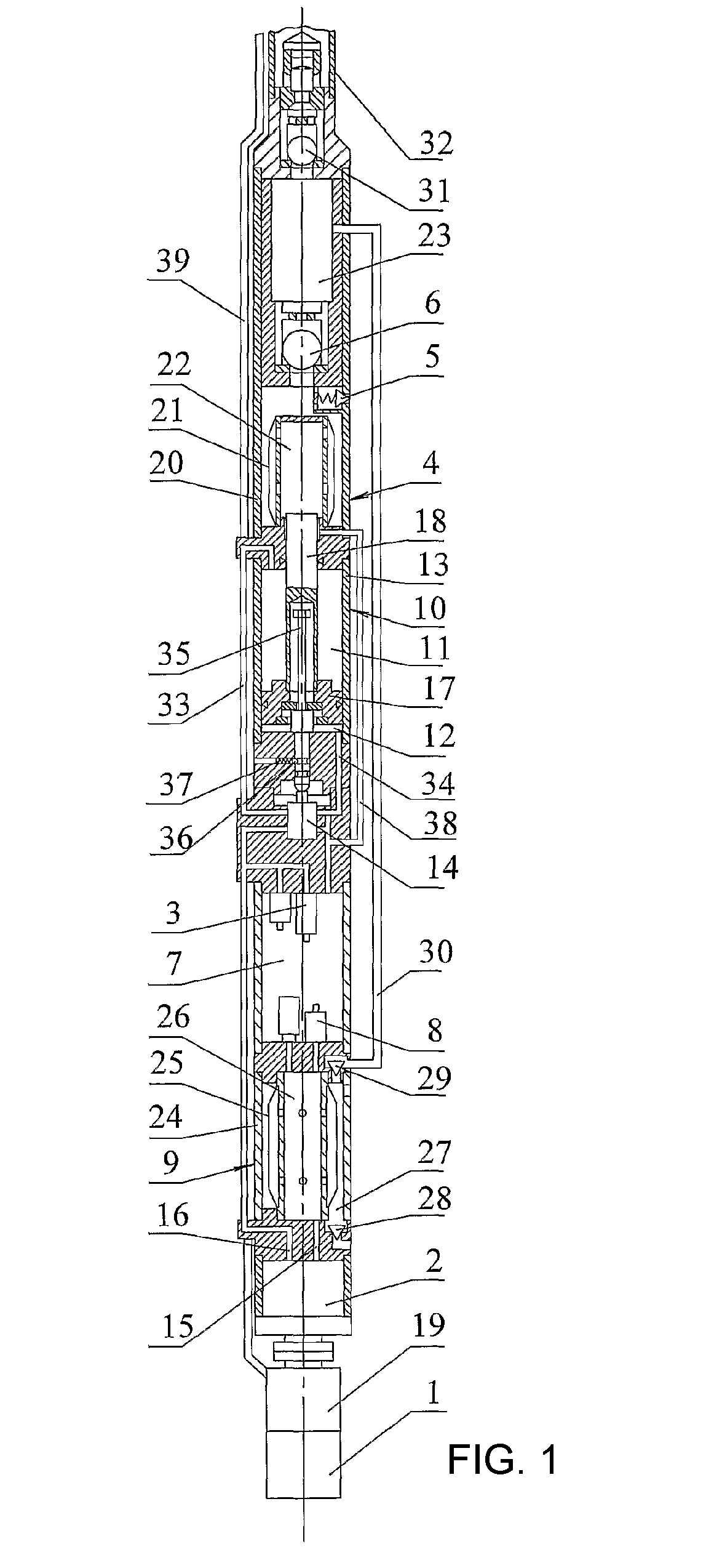
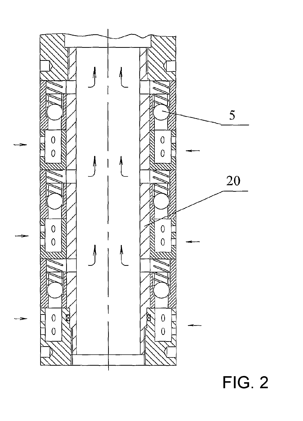
[0011]The electric hydraulically actuated well pump consists of submersible electric motor 1, engine-driven oil pump 2, plunger working pump 4 with suction 5 and pressure 6 valves, oil tank 7 with fine media oil filters 8, oil expansion joint 9 and hydraulic motor 10, and head-piston 11 and bottom-piston 12 chambers of cylinder 13, which are connected through control valve 14 to the suction 15 and pressure 16 sides of oil pump 2, (the latter of which is equipped with safety valve 3), and piston 17 of hydraulic motor 10 is connected to plunger 18 of working pump 4. Electric motor 1 is equipped with protector 19, the shaft of which kinematically connects the shaft of electric motor 1 to the shaft of engine-driven oil pump 2. An axial piston pump is used as engine-driven oil pump 2, and cylinder 20 of plunger working pump 4 is equipped with hermetic cylindrical flexible diaphragm 21, which forms chamber 22 filled with oil in cylinder 20. Plunger 18 of working pump 4 is capable of recip...


PUM


Abstract

A downhole electric driven pump unit for oil production comprises a submersible electric motor (1), a driven oil pump (2), a working plunger pump (4), an oil tank (7) provided with a secondary oil filter (8), an oil volume expansion compensator (9) and a hydraulic engine (10). Above-piston and under-piston cavities (11, 12) of the hydraulic engine cylinder (13) are connected to the oil pump suction and discharge sides (15, 16) through a distributor (14). The hydraulic engine piston (17) is connected to the plunger (18) of the working pump. The electric motor is provided with a protector (19) and is cinematically linked with the driven pump shaft by means of the protector shaft. The working pump cylinder (20) is provided with a sealed cylindrical diaphragm (21) made of elastic material such that oil filled cavity (22) is formed. The working pump plunger (18) is mounted such that it is reciprocatingly displaceable in the cavity (22). A pressure valve (31) is arranged above the discharge valve (6) such that a cavity (23) is formed. The compensator (6) is in the form of a cylinder (24) provided with a cylindrical diaphragm (25) which is placed therein such that an internal sealed cavity (26) communicating with the oil tank (7) and an annular cavity (27) is formed. Said invention makes it possible to increase the performance factor and reliability of the unit.

Description

[0001]The invention applies to the field of mechanical engineering, particularly to well pumps for extracting oil.PREVIOUS TECHNOLOGY[0002]Electric hydraulically actuated diaphragm well pump for extracting oil (see Patent RU No. 2062906, Class F 04 B 47 / 06, Jun. 27, 1996).[0003]The known design has shortcomings of low efficiency, short service life for the flexible plane diaphragm due to high stroke frequency, low pump lift performance, inability to extract oil with low water cut due to the suction valves' poor carrying capacity.[0004]The closest technical solution is the electric hydraulically actuated well pump consisting of a submersible electric motor, engine-driven oil pump, plunger working pump with suction and pressure valves, oil tank with fine media oil filters, oil expansion joint and hydraulic motor. Head-piston and bottom-piston cylinder chambers of the hydraulic motor are connected through the control valve to the suction and pressure sides of the oil pump (the latter o...

Claims


Application Information

Patent Timeline
Patent Type & Authority Applications(United States)
IPC IPC(8): F04B47/08
CPCF04B47/08E21B43/128
Inventor PONOMAREV, ANATOLY KONSTANTINOVICHANTONNIKOV, ALEKSANDR NIKOLAEVICH
Owner PONOMAREV ANATOLY KONSTANTINOVICH
Why Eureka
Try Eureka