Ion transport device and modes of operation thereof
- Summary
- Abstract
- Description
- Claims
- Application Information
AI Technical Summary
Benefits of technology
Problems solved by technology
Method used
Image
Examples
first embodiment
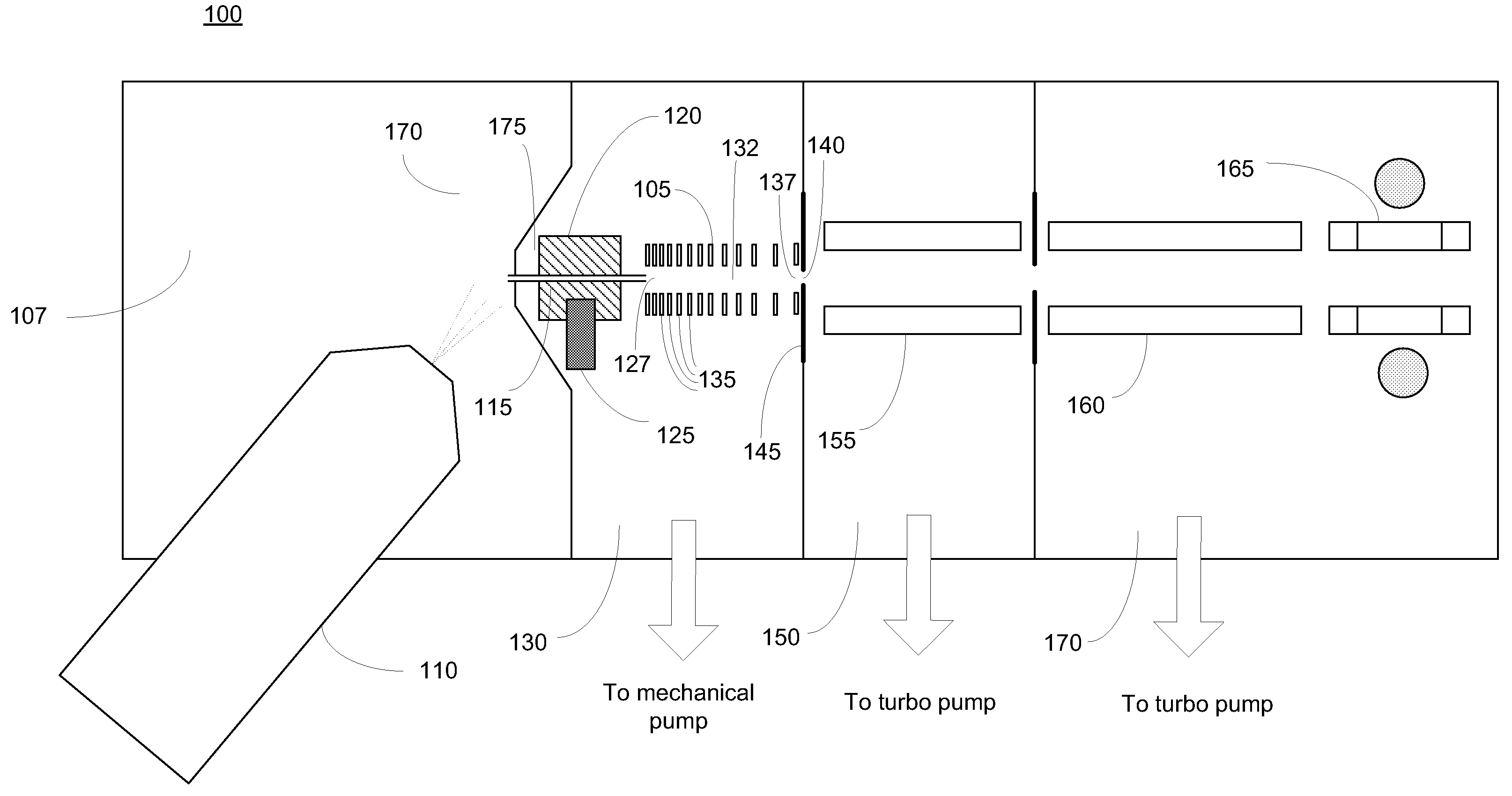
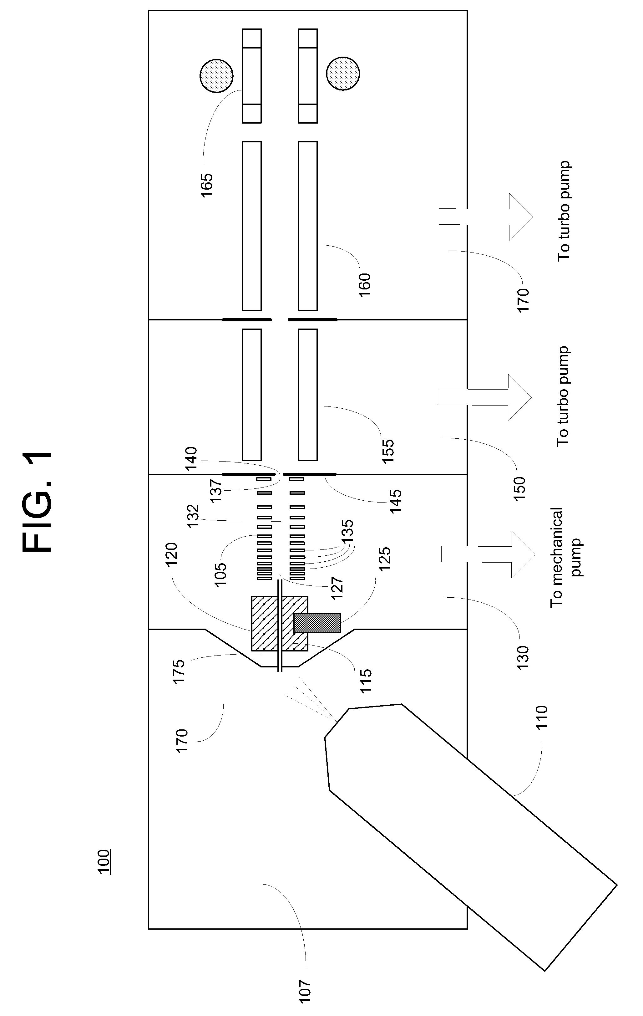
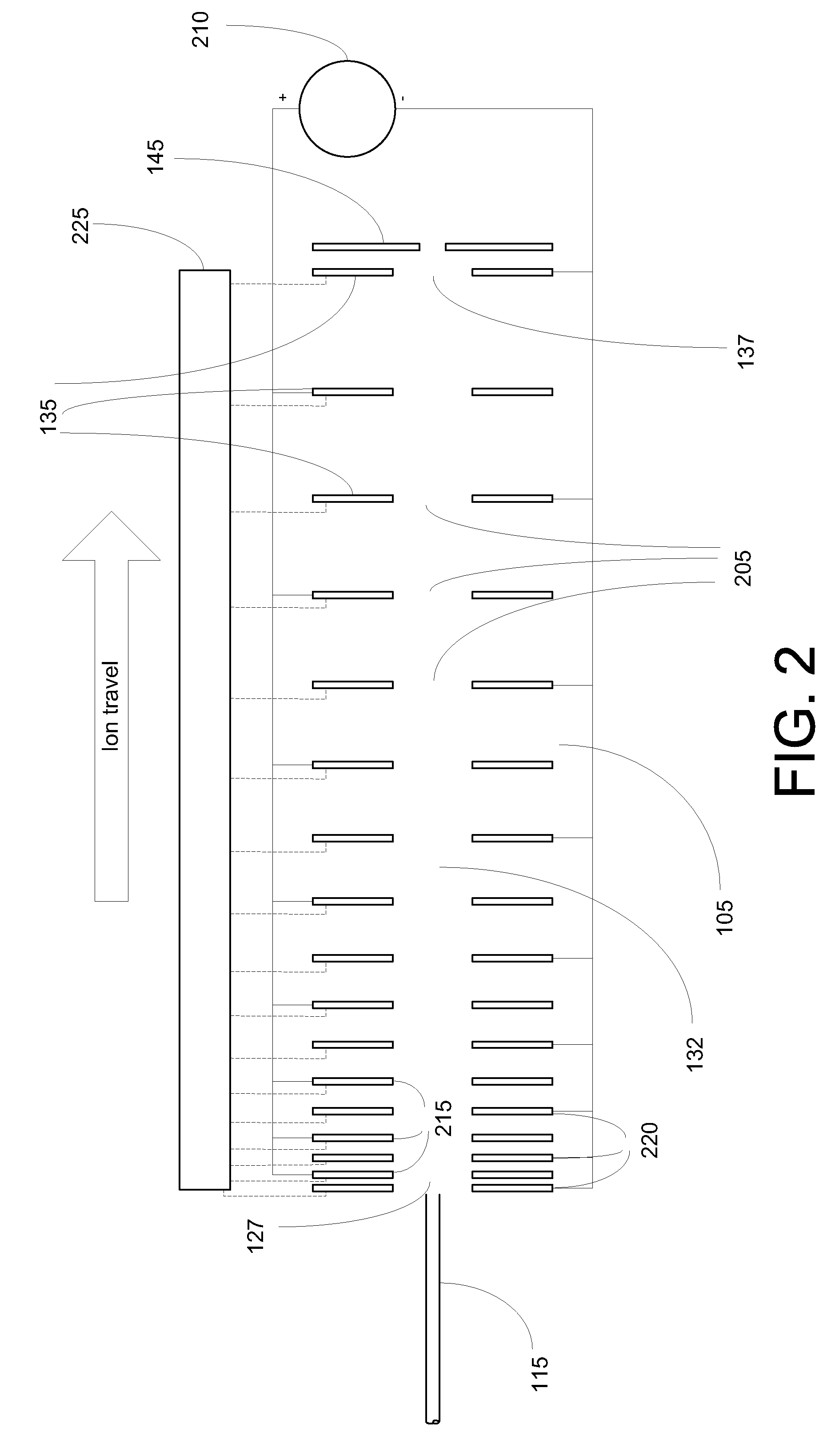
[0020]FIG. 1 is a schematic depiction of a mass spectrometer 100 incorporating an ion transport device 105 constructed in accordance with the invention. Analyte ions may be formed by electrospraying a sample solution into an ionization chamber 107 via an electrospray probe 110. For an ion source that utilizes the electrospray technique, ionization chamber 107 will generally be maintained at or near atmospheric pressure. The analyte ions, together with background gas and partially desolvated droplets, flow into the inlet end of a conventional ion transfer tube 115 (e.g., a narrow-bore capillary tube) and traverse the length of the tube under the influence of a pressure gradient. In order to increase ion throughput from ionization chamber 107, multiple ion flow channels may be provided by substituting multiple capillaries or a divided flow path ion transfer tube for the single channel ion transfer tube depicted herein. Analyte ion transfer tube 115 is preferably held in good thermal c...
second embodiment
[0030]FIG. 5 depicts an ion transport device 500 constructed in accordance with the invention. In contrast to the FIG. 2 embodiment, electrodes 505, each of which is adapted with an identically sized aperture 507, are regularly spaced along the longitudinal axis. The electrodes 505 collectively define an ion channel 510. To generate the tapered radial field that promotes a high ion acceptance efficiency at device entrance 512 and tight focusing of the ion beam at device exit 515, the amplitude of oscillatory voltages applied to electrodes 505 increase in the direction of ion travel, such that each electrode 505 receives an oscillatory voltage of greater amplitude relative to electrodes in the upstream direction. This increase in oscillatory voltage amplitude is represented by the graph depicted in FIG. 5. The desired oscillatory voltages may be delivered through a set of attenuator circuits 520 coupled to oscillatory voltage source 525. In one implementation of ion transport device ...
PUM
| Property | Measurement | Unit |
|---|---|---|
| Pressure | aaaaa | aaaaa |
| Pressure | aaaaa | aaaaa |
| Time | aaaaa | aaaaa |
Abstract
Description
Claims
Application Information
 - R&D
- Intellectual Property
- Life Sciences
- Materials
- Tech Scout
- Unparalleled Data Quality
- Higher Quality Content
- 60% Fewer Hallucinations
Browse by: Latest US Patents, China's latest patents, Technical Efficacy Thesaurus, Application Domain, Technology Topic, Popular Technical Reports.
© 2025 PatSnap. All rights reserved.Legal|Privacy policy|Modern Slavery Act Transparency Statement|Sitemap|About US| Contact US: help@patsnap.com


