Well servicing combination unit

a combination unit and well technology, applied in the direction of borehole/well accessories, drilling casings, drilling pipes, etc., can solve the problems of limiting the equipment that each can drive, increasing the mass and volume of transportation, and limiting the number of integrated units

Inactive Publication Date: 2009-02-26
WISE WELL INTERVENTION SERVICES
View PDF7 Cites 33 Cited by
  • Summary
  • Abstract
  • Description
  • Claims
  • Application Information

AI Technical Summary

Benefits of technology

[0011]A single small engineless well servicing unit comprising:

Problems solved by technology

Separate, dedicated power sources for each unit drastically increases the mass and volume that must be transported.
Current power packs are horsepower limited, which limits the equipment that each can drive.
Even with a hydraulic power manifold to drive multiple units from a single engine, the horsepower limits how many can be integrated.
The requirement for multiple (or much larger) transportation units increases the transportation costs, time, and personnel required to bring the units to the well and run these services.
U.S. Pat. No. 6,230,805 (Vercaemer) teaches a method of hydraulic fracturing in which at least two separate fracturing fluid components are pumped downhole—one of said components being pumped downhole within coiled tubing—but does not teach how to accomplish this with a single compact unit in which all equipment is powered by an onsite engine and that also provides for the coil tubing operation and wireline inspection.
Also, no means for wireline inspection is provided.
The off-shore prior-art that has the same functionality as the present invention is larger, more expensive, and requires either multiple barges or ships—necessitating additional time and expense for set up and take down of ship to ship plumbing—or a larger, more expensive barge or ship that has a deeper draft and can therefore depart from and reach fewer locations.

Method used


Image

  • Well servicing combination unit
  • Well servicing combination unit
  • Well servicing combination unit

Examples


Embodiment Construction

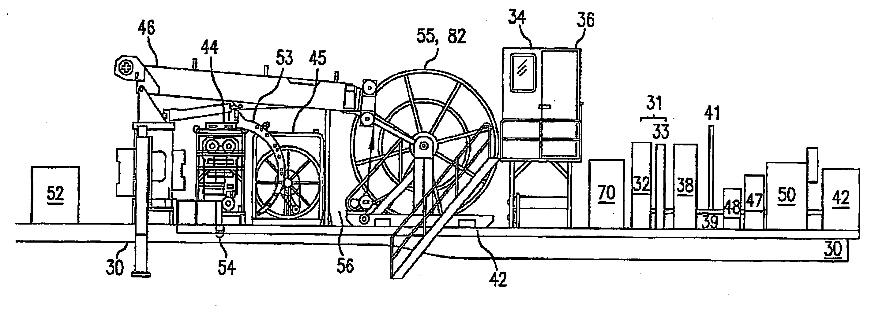
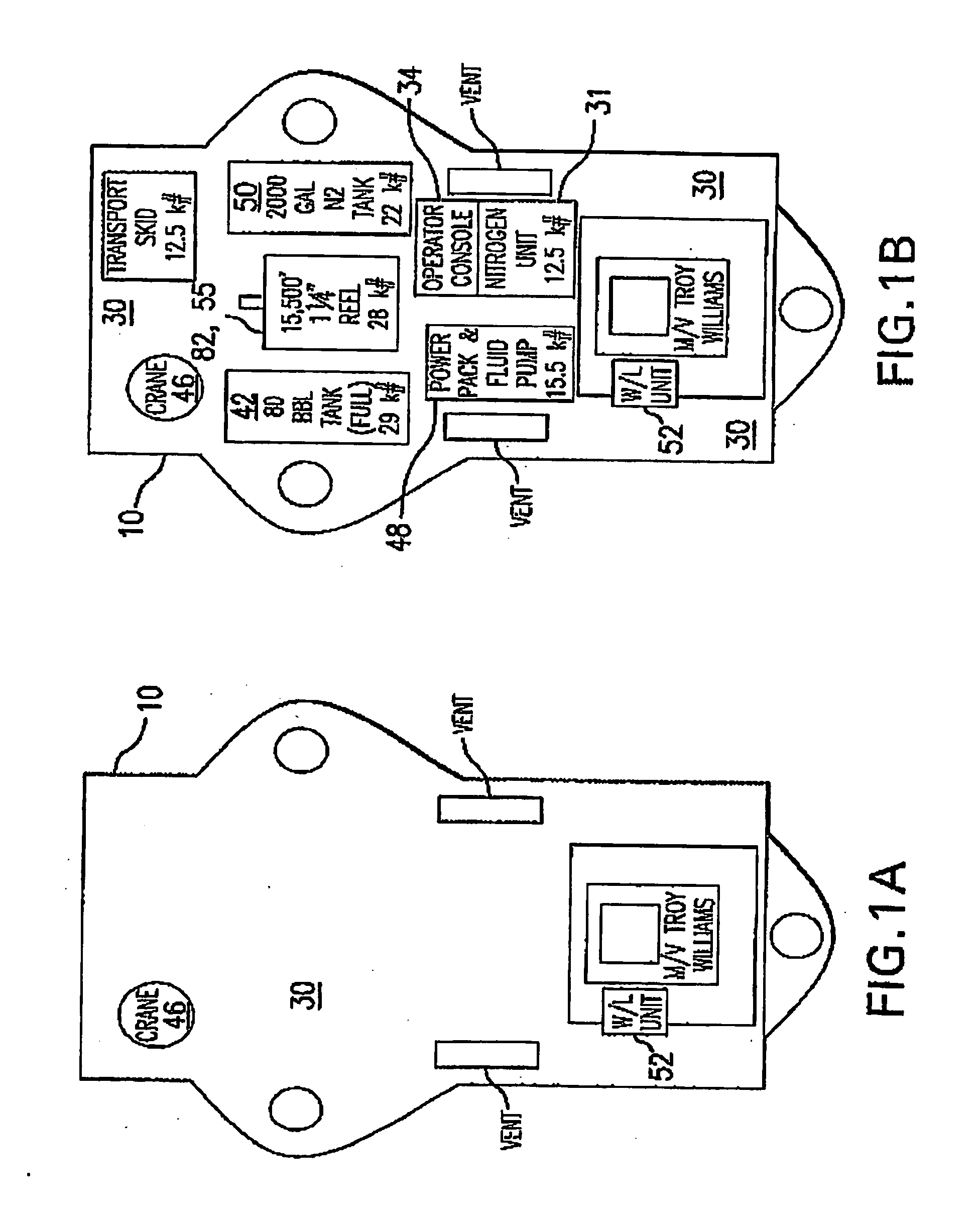
[0028]Referring now to FIG. 1, a top view of jack-up boat 10 having either a gasoline engine or a diesel engine is illustrated. Mounted on the boat deck 30 is nitrogen generator 31 (also shown in FIG. 4) that extracts nitrogen from the atmosphere to eliminate the need for (and the associated cost of) transporting and filling nitrogen tanks. Mounted to boat deck 30 are chemical storage tanks 42 that supply chemicals to blending tanks 50 where the chemicals arc mixed. The mixed chemicals flow to the well servicing fluid pump 48. The mixed chemicals may flow through the coil tubing 82, 50 to the well head. Wireline inspection unit 52 is mounted to deck 30. Also mounted on the deck 30 is control cabin 34 in which the electrical and hydraulic units 36 are controlled by a human operator. Components arc described in greater detail in the description of FIG. 2 below.

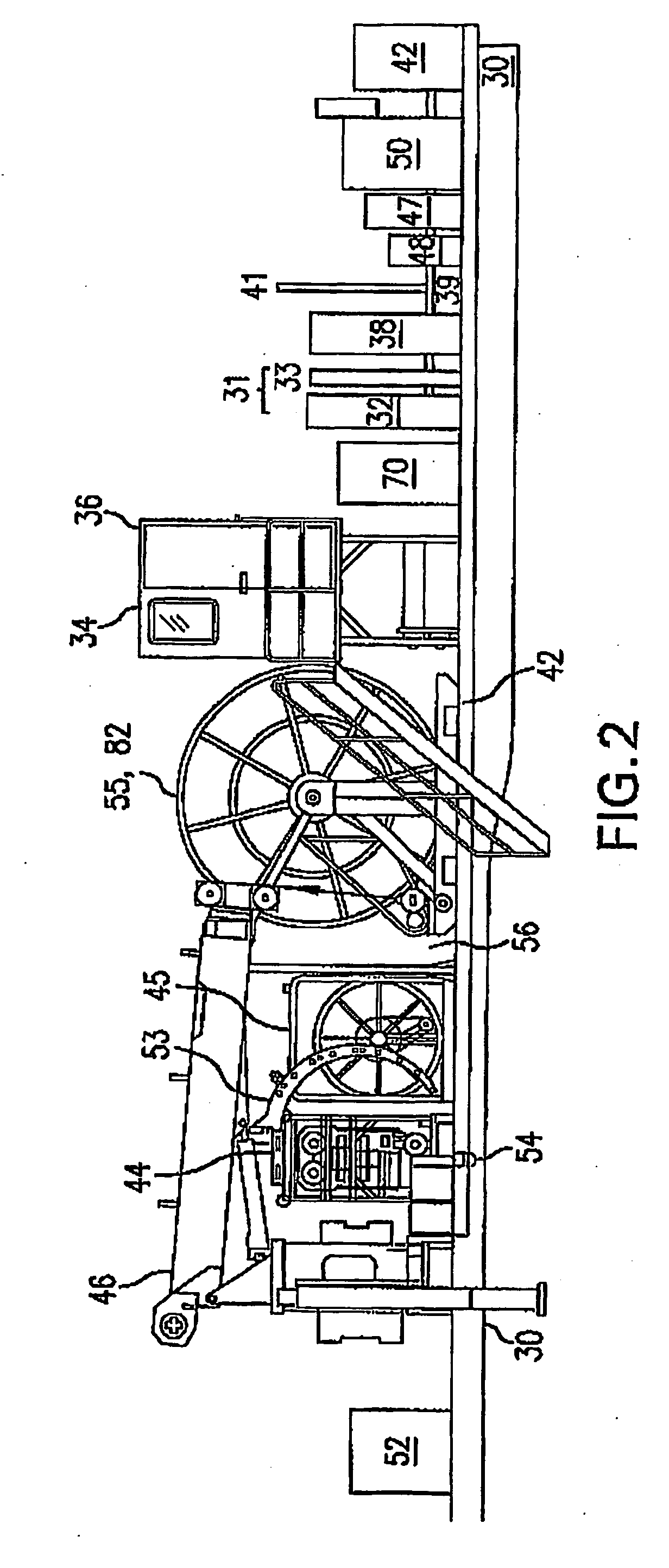
[0029]Referring now to FIG. 2, a diagram of a jack-up boat 10 is illustrated. Mounted on the boat deck 30 is a custom hydrauli...


PUM


Abstract

A single well servicing combination unit comprising: a hydraulic manifold removably connectable to the power-take-off of an external power source to drive a plurality of hydraulic pumps and motors that control a plurality of well servicing units mounted on said combination unit, said well servicing units being interconnectable by plumbing.

Description

FIELD[0001]This invention rotates, generally, to the treatment of oil and gas wells using fluids to increase the production capability of the wells, and more specifically, to providing for treatment of oil and gas wells with a means and apparatus that combines multiple unite—which may include: coiled tubing, nitrogen generation, fluid pumping, blending tanks, wireline inspection, and other units—into a single unit powered by an external source.BACKGROUND[0002]It is known in the art to use self-powered units to provide wireline inspection and workover operations using gaseous nitrogen to remove sand and / or water or other impediments to production of oil and gas wells. The prior art has not recognized that a single, relatively small, engineless unit requiring minimal set-up / take-down time can be provided with all of the equipment and accessories for tapping into an onsite power source to run a combined and integrated system that may include one or more of the following: coiled tubing ...

Claims


Application Information

Patent Timeline
Patent Type & Authority Applications(United States)
IPC IPC(8): E21B43/18
CPCE21B43/168E21B19/22
Inventor CRAWFORD, JAMES B.
Owner WISE WELL INTERVENTION SERVICES
Why Eureka
Try Eureka