
In-line filtration systems

a filtration system and filter technology, applied in the field of online analysis systems, can solve the problems of reducing the effective filtration area, affecting the operation efficiency of the analyzer, and affecting the accuracy of the analysis results, so as to improve the effective operation time and prevent cake formation in the filter

Inactive Publication Date: 2009-03-05
GENERAL ELECTRIC CO
View PDF8 Cites 13 Cited by
  • Summary
  • Abstract
  • Description
  • Claims
  • Application Information

AI Technical Summary

Benefits of technology

[0014]The present invention relates to a filtration system with a flip-flop, cross-flow function and to a filtration method, especially to a filtration system which uses a combination of cross-flow and dead end filtration to prevent cake formation in a filter. The present invention increases effective operation time and allows for continuous filtration operation without interruption.
[0015]Disclosed is a filtration system for processing samples for on-line analysis that increases time between filter changes while providing filtered samples that accurately represent the concentration of macromolecular species in industrial systems, including, but not limited to industrial water process systems. Additionally, the present invention provides for the system to capture representative solids at regular frequency and provide an on-line batch-wise sample concentration mechanism. This system can be tuned to capture material above the nominal pore size defined by the membrane, and flow times can be used to define the desired concentration factor.
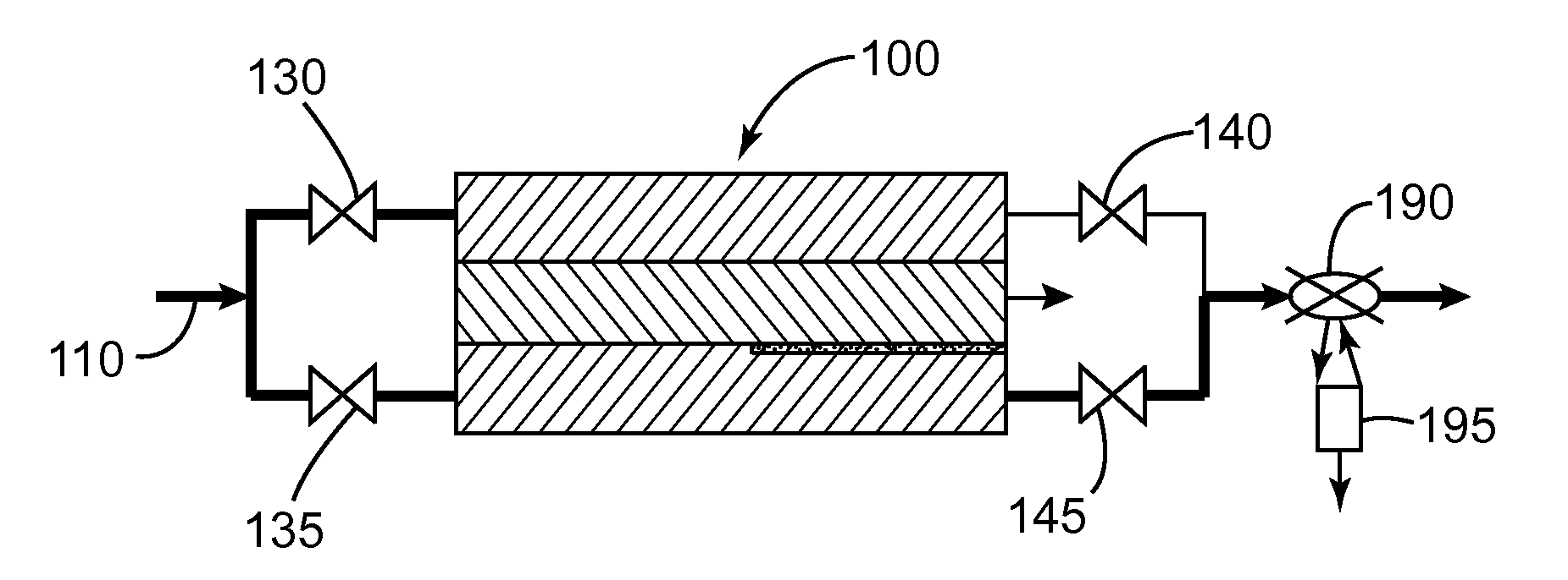
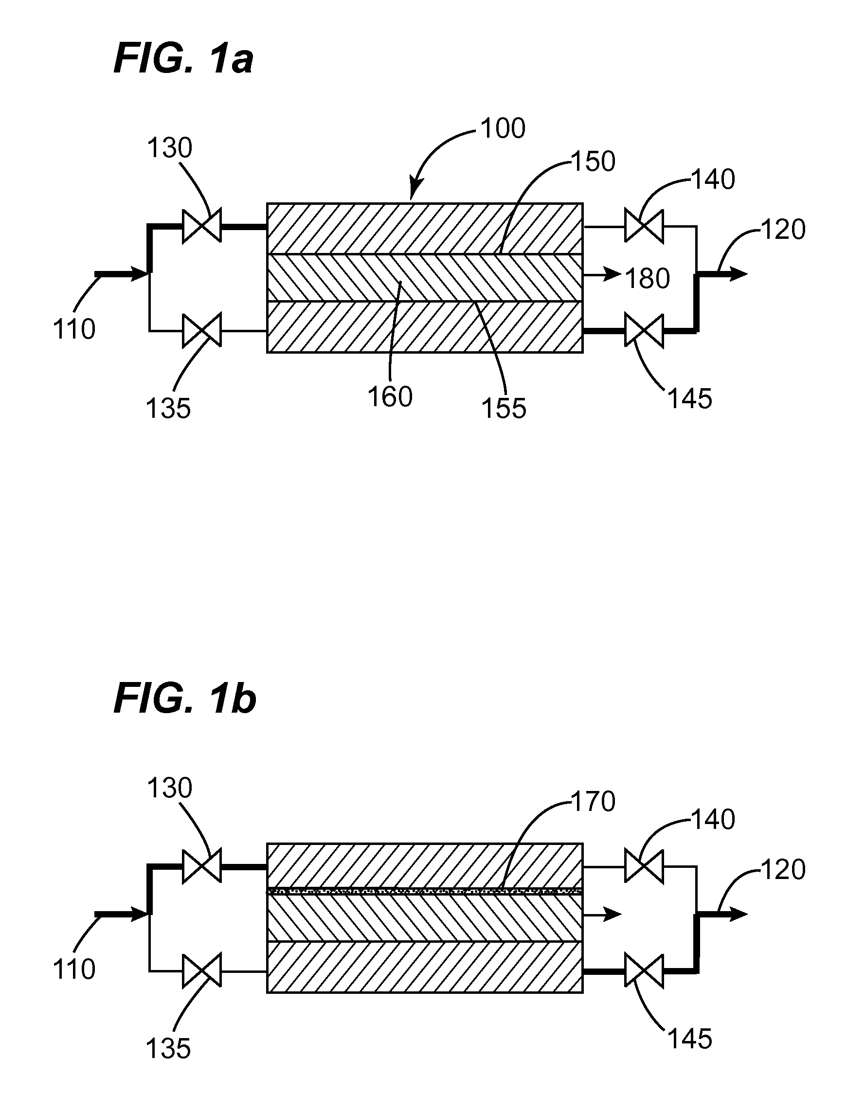
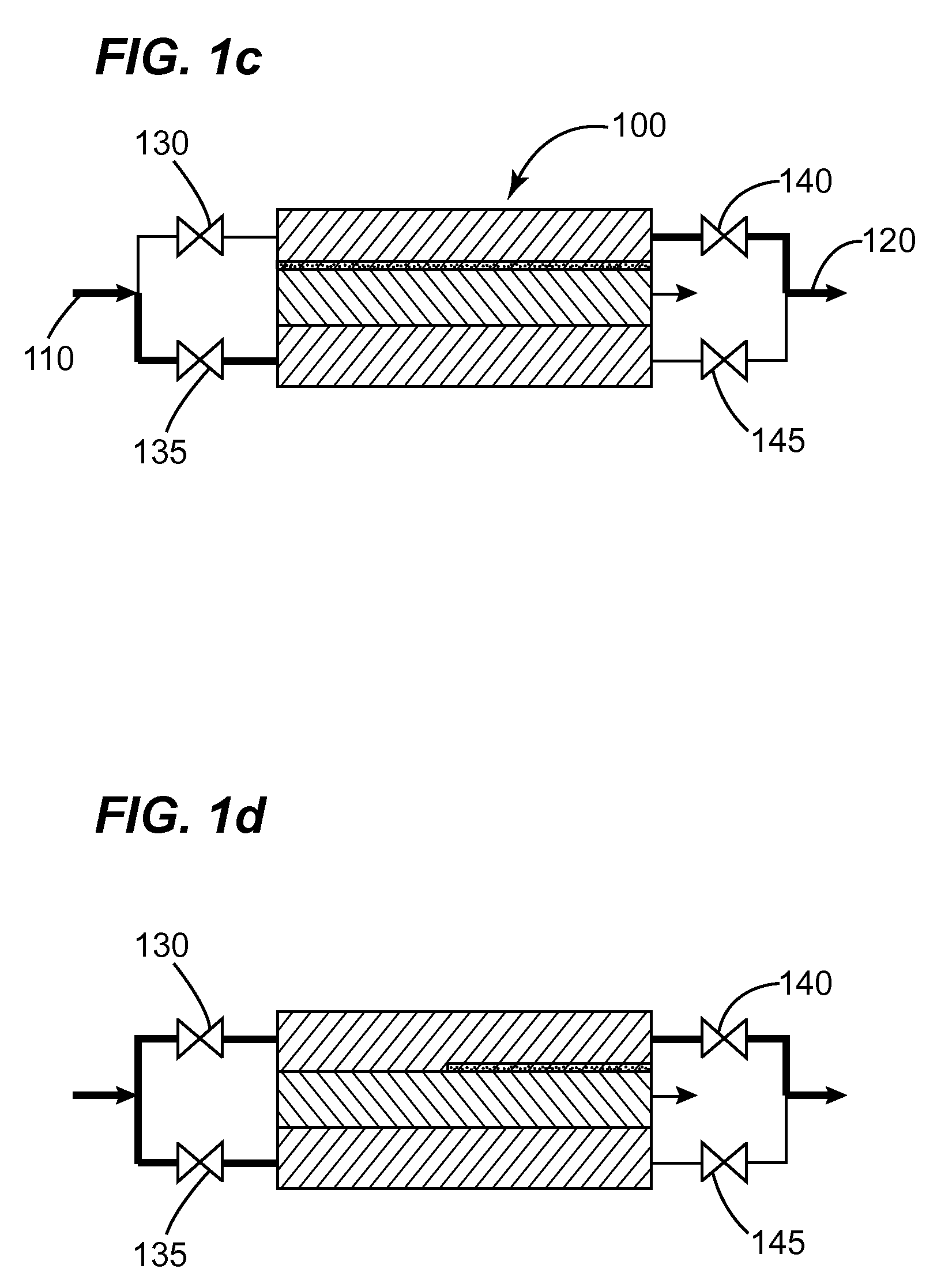
[0016]In one embodiment of the present invention, a filtration system for processing samples for on-line sample analysis with a flip-flop function that flips flow back and forth between the sides at a frequency that minimizes filter cake formation, prevents macromolecular adsorption, and provides filtered samples that accurately represent the concentration of macromolecular species in industrial water and process systems is disclosed. The filtration system comprises a supply line, two opposing filters with a central collection chamber, a central filtered sample line, a drain line, and a flow control system to control flow direction. The flip-flopping occurs at a frequency that prevents macromolecular adsorption and this frequency can be adjusted and tweaked until a best-case scenario is realized. This process results in macromolecular concentration gradients that can be maintained below acceptable tolerances, with the gradient tolerance defined by the flipping frequency designated in the system. A flow control system consisting of multiple solenoid valves can be used to achieve the flow direction regulation as described above. A combination of commercially available two-port valves and multiple-port valves can be chosen. Ideally, a specially designed manifold consisting of multiple channels and a single integrated multiple-port valve can be made to achieve an optimal flow control system that is specific to the flow regulation needs as described.
[0017]In another embodiment, a cross-flow function is added to the previously described flip-flop system. This system provides an additional cross flow of fluids at a higher velocity to shear materials off the surface of the exit or drain line side of a dual filter while the sample filter is being performed on the opposite side. The combination of backflow through the membrane as a result of the flip-flopping and cross-flow across the membrane enhances and speeds cake removal, allowing the membrane to return to a cleaner state sooner. This allows for longer run times than those obtained with a system with only a backflow design or only a cross-flow design. The combination of flip-flop and cross flow enhances the lifetime of the filtration system. The integration of the alternating cross flow where the sample is extracted between two membranes allows for both continuous sampling and continuous cleaning.

Problems solved by technology

This situation results in impurities, formation of a cake, and blocking on the openings of the filter, which cause the effective filtration area to be reduced.
This mode of operation is used for high solids feeds because of the risk of blinding.
With dead end filtration, solids material can quickly block or blind the filter surface.
However, these approaches can prove problematic for on-line analyzers because of plugging of the filters by particulate and suspended material.
And in fact, this becomes even more problematic as the pore size of the filter is reduced.
The cross-flow filter design is less prone to plugging than a dead end filter, however, cross-flow filtration can still be susceptible to particulate accumulation and pluggage, but to a lesser degree.
However, this approach requires costly manual filter replacement at inconvenient intervals.
Although frequent filter changes address some of the concerns, it does not address all issues that arise.
In particular, there is still the issue of accumulating materials on a filter that creates a sink for materials known to absorb or be trapped by the forming particulate beds.
Therefore, the concentration that passes through the in-line filter into the detection system can actually decrease over time and produce an artificially decreasing response.
This sample gradient can produce on-line signals that do not accurately represent the concentration in the original system.
There are systems that can minimize macromolecular adsorption by frequently changing filters, but this often requires frequent operator intervention.
In addition, these methods can be both time-consuming and costly.

Method used


Image

  • In-line filtration systems
  • In-line filtration systems
  • In-line filtration systems

Examples


example 1

[0059]A functioning flip-flop, cross-flow prototype has been built and shown to work in the lab with high solids material and 30 um screens as filters. The size of the membrane is defined by the particle size distribution in the sample and the desired flowrate required for the analyzer. There are unlimited combinations of membrane pore sizes and flows that may be used. Examples of high solids materials include, but are not limited to, clay, silt, sand, silicates, diatomaceous earth, glass or silica beads.

example 2

[0060]A cooling tower water sample is pumped through a conventional cross-flow filter with a 0.22 micron polyethersulfone membrane at a constant filtrate flow rate of 2 ml / min filtrate flow rate and a 1000 ml / min of cross flow. The sample water contains 7.2 to 24 ppm GE cooling tower treatment polymer. In the first 2 days, the polymer passage through the membrane was 88%. After 6 days in operation, a thin cake layer formed on the membrane surface and the polymer concentration in the filtered water was reduced to 71% of that in the unfiltered sample stream. A brief backwash was conducted on the seventh day and the polymer passage was resumed to the initial value 88%. A series of tests were conducted for different water samples and at different filtrate flow rates. It was observed that the higher filtrate flow rate required the higher backwash frequency. This demonstrates that although the filter can provide a sufficient volumetric flow to an analyzer, the cake formation on the membra...


PUM

PropertyMeasurementUnit
filtrate flow rateaaaaaaaaaa
concentrationaaaaaaaaaa

Abstract

A filtration system is disclosed that uses a combination of dead end filtration across opposing membranes with a sample take-off in the middle and cross-flow to prevent cake formation on these opposing filters. In one embodiment is a system that uses opposing filters with a central collection chamber that flips flow back and forth between the sides at a frequency that minimizes filter cake formation. In another embodiment, a combination flip-flip, cross flow system is disclosed. An additional embodiment discloses an actuator valve driven sampling system, in which valves collect the cross flow / counter flow filter cake samples as they are liberated from a filter surface and a quick through filter fluid pulse loosens the sample cake from the filter material. The invention increases effective operation time, allows for continuous filtration operation without interruption, and provides filtered samples that accurately represent the concentration of macromolecular species in industrial systems.

Description

CROSS REFERENCE TO RELATED APPLICATIONS[0001]This application claims priority from U.S. Provisional Application Ser. No. 60 / 969774 entitled “IN-LINE FILTRATION SYSTEM” filed on Sep. 4, 2007, the entirety of which is incorporated by reference herein.BACKGROUND OF THE INVENTION[0002]1. Field of the Invention[0003]The present invention relates to an on-line analysis system for use in industrial processes, including, but not limited to industrial water process systems. In particular, it relates to a filtration system with a flip-flop function and a filtration system with a combination flip-flop, cross-flow function.[0004]2. Description of Related Art[0005]Many different types of industrial or commercial operations rely on large quantities of water for various reasons, such as for cooling systems, or to produce large quantities of wastewater, which need to be treated. These industries include, but are not limited to, agriculture, petroleum, chemical, pharmaceutical, mining, metal plating...

Claims


Application Information

Patent Timeline
Patent Type & Authority Applications(United States)
IPC IPC(8): B01D61/58B01D35/22B01D35/157C02F1/00B01D35/30B01D36/00
CPCB01D61/18B01D65/08B01D2315/08C02F2303/16B01D2321/2083C02F1/44B01D2315/10
Inventor BARRETT, KENNETH CHARLESBOYETTE, SCOTTXIAO, CAIBINWAN, ZHAOYANG
Owner GENERAL ELECTRIC CO
Learn More