Method for generating low color temperature light and light emitting device adopting the same

a technology of light emitting device and low color temperature, which is applied in the direction of discharge tube/lamp details, discharge tube luminescent composition, discharge tube luminescent screen, etc., can solve the problems of high cost and complexity of peripheral circuit design, increase the complexity of manufacturing process and led lamp cost, and release of large amount of energy. , to achieve the effect of low cost, long life and energy saving

Inactive Publication Date: 2009-03-12
HE SHAN LIDE ELECTRONICS ENTERPRISE CO LTD
View PDF16 Cites 36 Cited by
  • Summary
  • Abstract
  • Description
  • Claims
  • Application Information

AI Technical Summary

Benefits of technology

[0009]It is an object of the present invention to provide a method for generating low color temperature light, in which the warm light

Problems solved by technology

However, emission light with single wavelength of LED lamp can only be used in the specific decoration situation, and therefore a LED lamp with mixed colors used in various situations is the common object of the companies in this field.
1. LEDs of red, green and blue colors are encapsulated in one bulb, and an external circuit is provided for regulating the power of the tricolor LEDs. Thus, white light or near-white light could be obtained. In this structure, the powers of the three LEDs should be controlled separately, which results in the high complexity and costs for designing the peripheral circuit.
2. A LED emitting the first wavelength light (i.e. a blue LED) and a LED emitting the second wavelength light (i.e. a red LED) are used, and then the two LEDs are covered with yellow phosphor. After the light with the first wavelength irradiates on the yellow phosphor, one portion of the light travels through the yellow phosphor, while the rest of the light remains within the yellow phosphor to excite yellow light. The fist wavelength light (i.e. the blue light) and the second wavelength light (i.e. the red light) along with the yellow light are mixed together to generate white light or near-white light. In this structure, the desired voltage o

Method used


Image

  • Method for generating low color temperature light and light emitting device adopting the same
  • Method for generating low color temperature light and light emitting device adopting the same
  • Method for generating low color temperature light and light emitting device adopting the same

Examples


Embodiment Construction

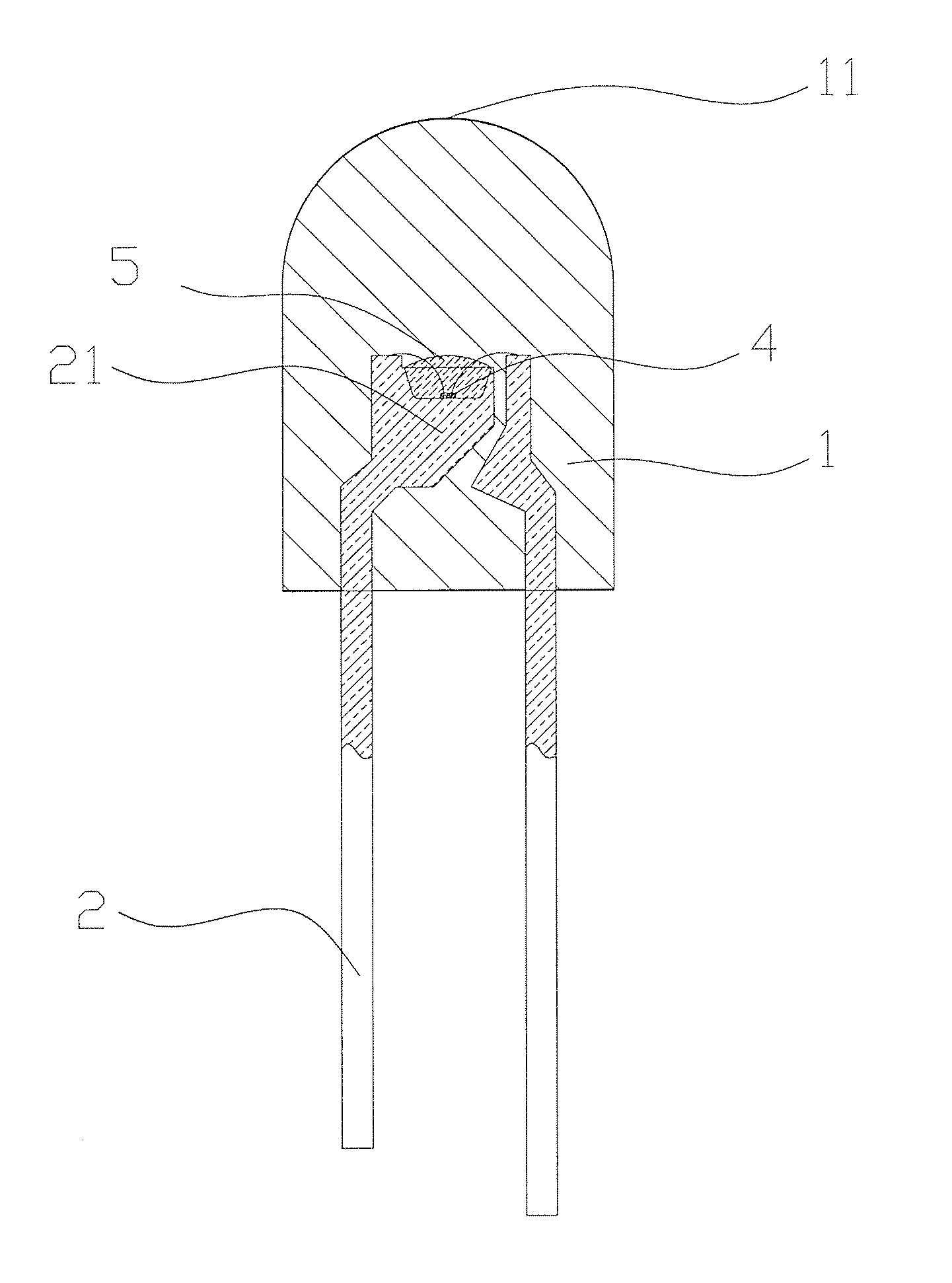
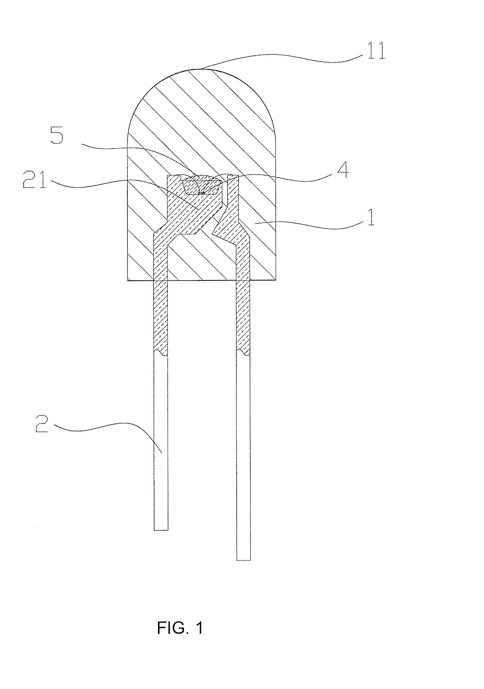
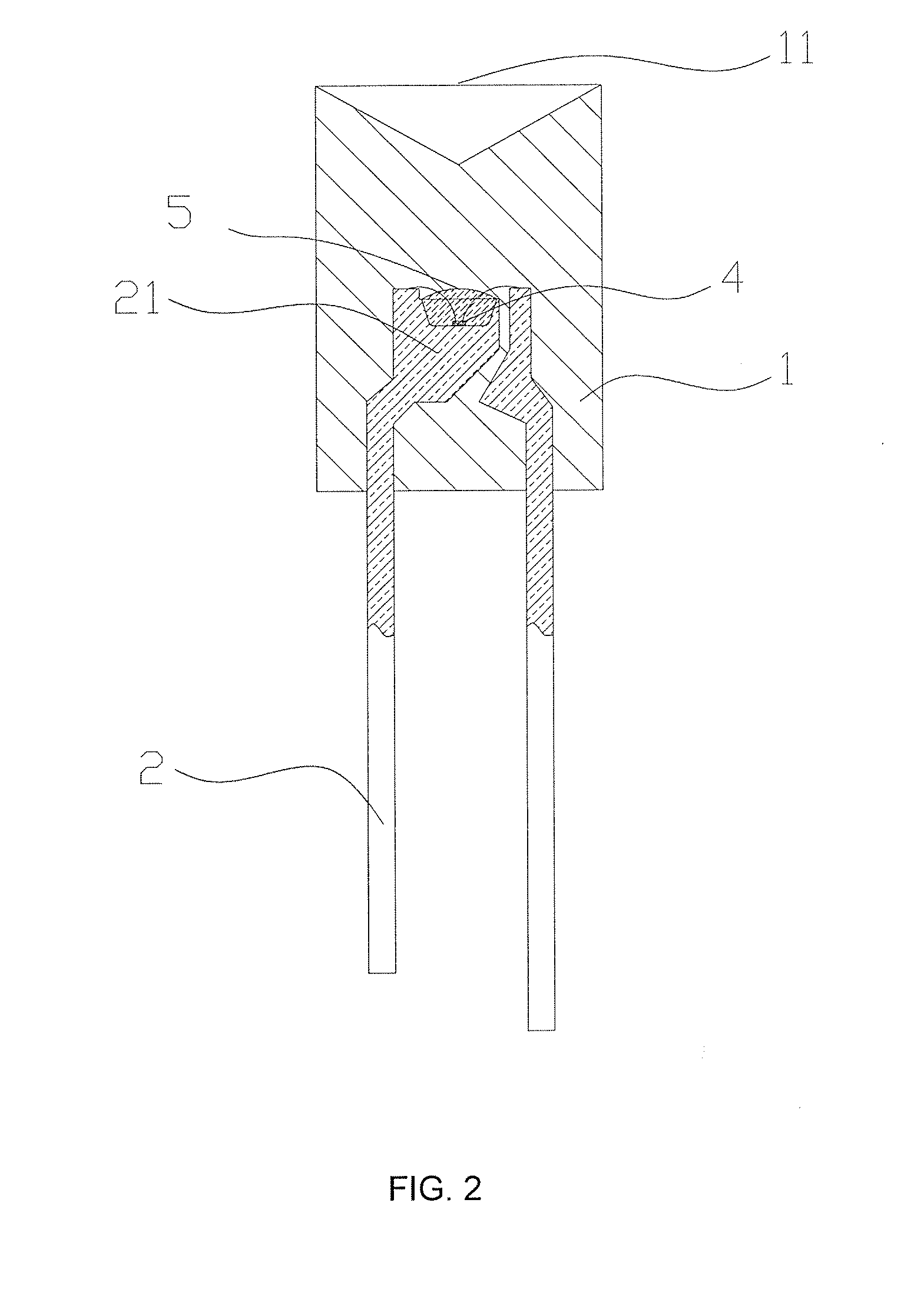
[0038]Referring to FIG. 1, a light emitting device for low color temperature light includes a casing being formed of a package colloid 1 of epoxy resin or other plastic materials. The package colloid 1 is provided with a LED component 4 inside. The LED component 4 is supported and connected to the external power supply by an electrode lead 2. The first wavelength light B is emitted by the LED component 4 with the peak wavelength ranging from 460 nm to 500 nm. The LED component 4 is covered by the phosphor 5 represented by the general formula A2SiO4 :Eu2+, D, wherein A is one of the elements selecting from the group consisting of Sr, Ca, Mg, Zn, Cd and I, D is one of the elements selecting from the group consisting of F, Cl, Br, I, P, S and N. The phosphor 5 can absorb a portion of the first wavelength light B and can be excited to generate the second wavelength light R with the peak wavelength ranging from 590-630 nm. After the electrode lead 2 is connected to the power supply, the ...


PUM


Abstract

A method for generating low color temperature light and a light emitting device adopting the same, comprise a LED component, phosphor capable to be excited by the emission light of the LED component, and a package colloid for encapsulating the LED component and the phosphor, wherein the package colloid is provided with a electrode lead for connecting the LED component with the external power supply, the peak wavelength of emission light of the LED light is 460-500 nm, the peak wavelength of emission light of the excited phosphor is 580-630 nm. The present invention only use one chip and one kind of phosphor to generate the low color temperature light which is of the same effect as that of the minitype tungsten lamp or the high pressure sodium lamp, and is of advantages including energy saving, low cost and environmental protection, etc. The present invention can be widely used in the manufacturing process of LED lamp of low color temperature, especially in the manufacturing the mini LED bulb.

Description

BACKGROUND OF THE INVENTION[0001]The present invention relates to a method for generating the light of LED lamp, in particular to a method for generating low color temperature light.[0002]The present invention further relates to a light emitting device, in particular to a light emitting device for low color temperature light.[0003]The simplest known LED may comprise a P-type semiconductor, a N-type semiconductor and a P-N junction between them. When the current travels through the LED, charge carriers (i.e. electron and hole) are generated in the P-N junction. Energy will be released in the form of photons as the electron and the cavity join together. Specified chemical materials may be added in the P-N junction so as to allow the light of specified color could be emitted by the LED lamp. For example, if InGaN is employed, the first wavelength light could be generated, and if GaN is employed, green light could be generated. The LED lamp is formed by encapsulating the LED with anode ...

Claims


Application Information

Patent Timeline
IPC IPC(8): H01J1/62
CPCC09K11/7734H01L33/483H05B33/14H01L33/54H01L33/502H01L2924/181H01L2224/48091H01L2224/48247H01L2224/48257H01L2224/8592C09K11/77342H01L2924/00012H01L2924/00014
Inventor FAN, BEN
Owner HE SHAN LIDE ELECTRONICS ENTERPRISE CO LTD
Why Eureka
Try Eureka