Particle sensor with wide linear range

a particle sensor and linear range technology, applied in the field of biomass and growth rate monitoring, can solve the problems of inability to conduct non-invasive measurements in many applications, the range of linearity achieved is still too limited for many applications, and the effect of adding more particles is non-additive, so as to reduce the sensitivity to the thickness of the container wall and rapid measurement of particle concentration

Active Publication Date: 2009-03-19
ABER INSTR INC
View PDF38 Cites 35 Cited by
  • Summary
  • Abstract
  • Description
  • Claims
  • Application Information

AI Technical Summary

Benefits of technology

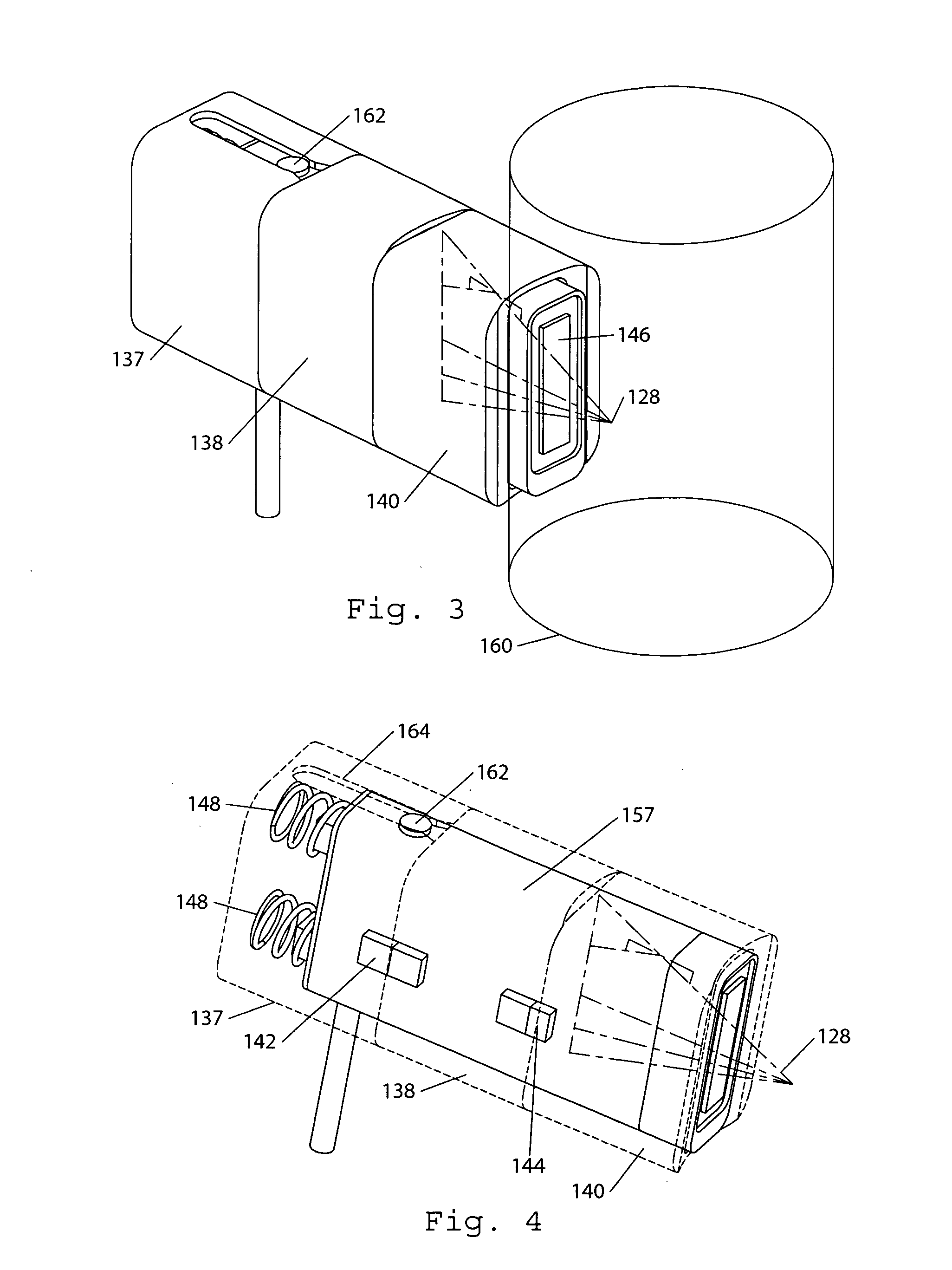
[0015]In yet other embodiments of the invention, the sensor is designed to be manually placed in close proximity to a vessel, such as a shake flask. A rapid measurement of particle concentration can be activated by contact with the vessel. In...

Problems solved by technology

On the other hand, when the mean distance between particles is small compared to the distance between the source and detector, the effect of adding more particles will be non-additive due to multiple scattering and the screening effect of particles aligned along the same radiation path.
However, even in such attempts the range of linearity that is achieved is still too limited for many applications.
Furthermore, the optical arrangement required to measure both transmission and reflectance would make it difficult or impossible to conduct measurements non-invasively in many applications.
For example, cells can be genetically modified to produce high yields of chemicals that would otherwise be difficult, expensive, or impossible to synthesize.
Unfortunately, the non-linear response of currently available sensors to biomass, makes accurate estimation of growth rate difficult or impossible.
As the nutrient supply relative to the biomass diminishes, the growth of cell culture will slow.
Unfortunately, methods of continuously and reliably measuring the growth of cells ...

Method used


Image

  • Particle sensor with wide linear range
  • Particle sensor with wide linear range
  • Particle sensor with wide linear range

Examples


examples

[0134]The following are examples of methods and use of devices of the invention (e.g., for determination of particle concentration). It will be appreciated that such descriptions and examples are not necessarily limiting upon the current systems, methods, etc. and their use unless specifically stated to be so.

[0135]Example of Algorithm Applied to Reflectance Measurement of Biomass

[0136]In this example, some of the algorithms of the present invention are applied to experimentally measured reflectance data. Measurements were made through the glass wall of a vessel containing a wide range of concentrations of Saccharomyces cerevisiae suspended in isotonic (0.9% w / v) saline. Such measurements can thus be used to determine offsets / multiplication factors to apply to measurement of unknown samples. See above. In the sensor used for this example, the source was a Vertical Cavity Surface Emitting Laser (VCSEL) emitting approximately 3 mW of power at 850 nm with a 3 degree divergence (Part No...


PUM


Abstract

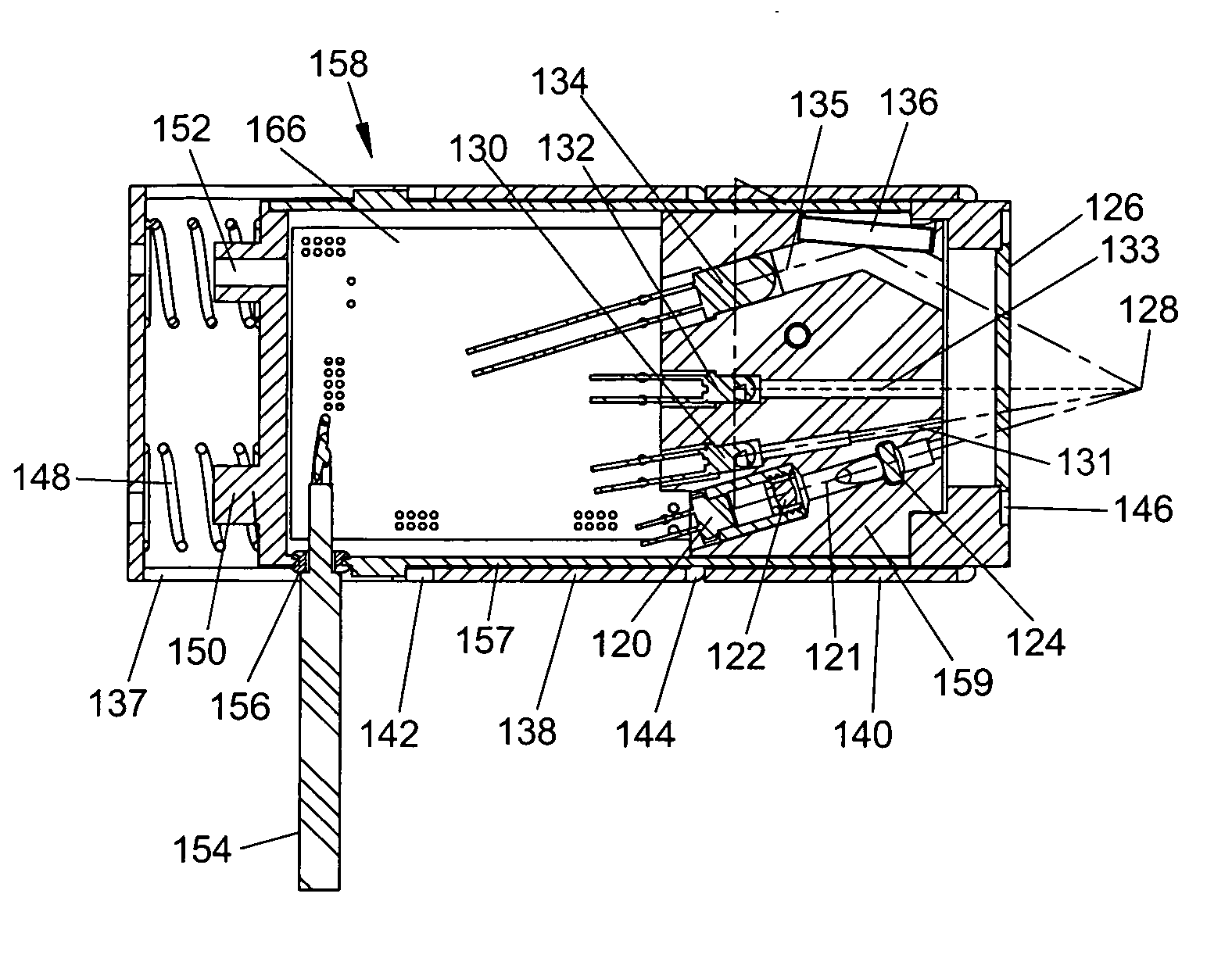
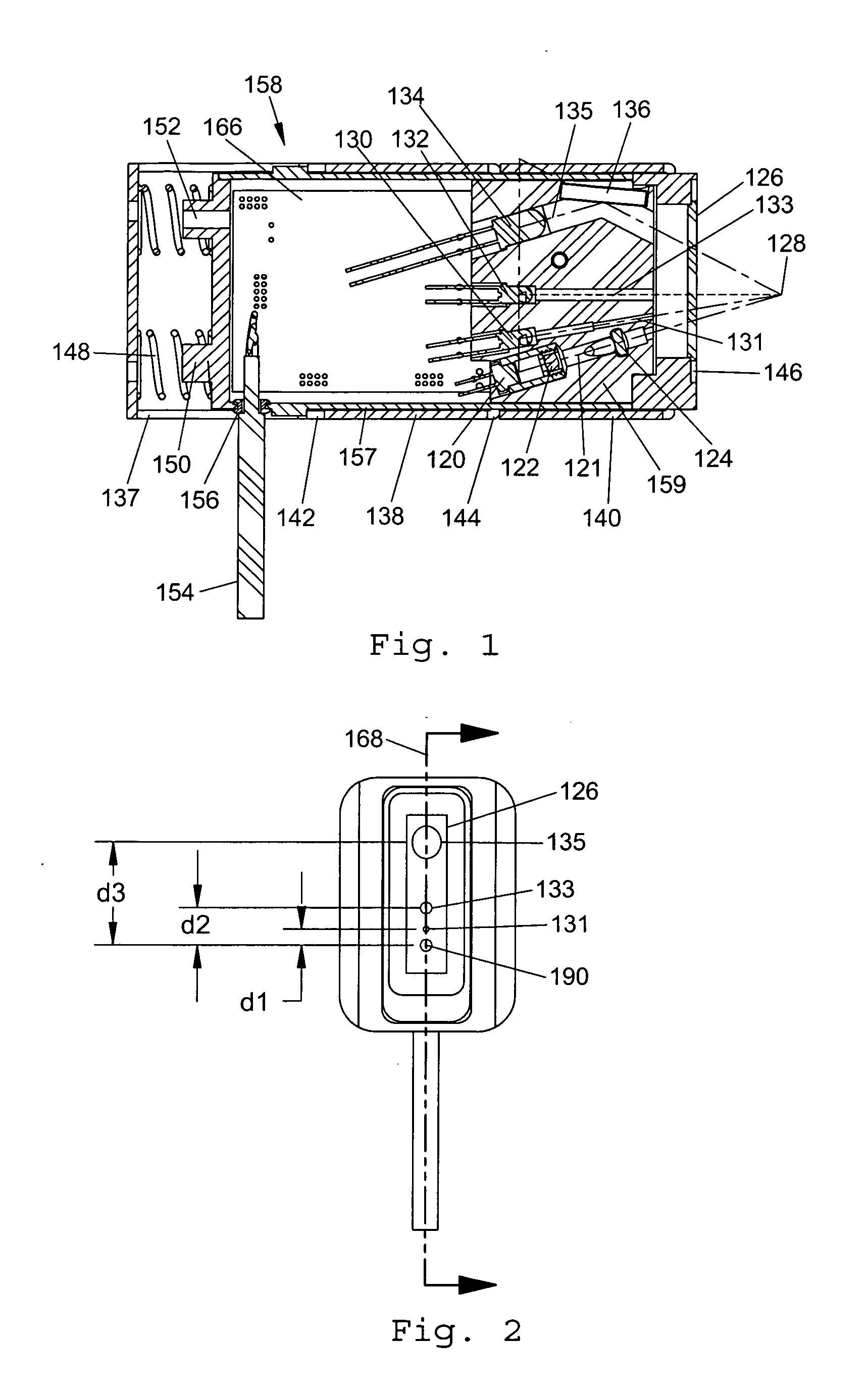
This invention provides a novel methods and devices for measurement of particle concentration or changes in particle concentration over a wide linear range. The invention comprises one or more radiation sources and one or more detectors contained in a housing which is interfaced to a medium containing particulate matter. The one or more radiation sources are directed into the medium, scattered or transmitted by the particulate matter, and then some portion of the radiation is detected by the one or more detectors. Methods for confining the measurement to a specific volume within the medium are described. Algorithms are provided for combining the signals generated by multiple source-detector pairs in a manner that results in a wide linear range of response to changes in particle concentration. In one embodiment the sensor provides non-invasive measurements of biomass in a bioreactor. In another embodiment an immersible probe design is described, which may be suited for one-time use. In an addition embodiment, a sensor is provided which is well suited to the rapid sequential measurement of particle concentration in multiple vessels, such as assessment of biomass in series of shake flasks.

Description

CROSS-REFERENCE TO RELATED APPLICATIONS[0001]This application is related to, and claims benefit of, U.S. Provisional Patent Application Ser. No. 60 / 962,350 filed Jul. 28, 2007, the disclosure of which is incorporated herein by reference in its entirety for all purposes.FIELD OF INVENTION[0002]The present invention relates generally to methods and devices for determining particle concentration in a medium through use of radiation sensors and detectors and algorithms to extend the linear range between particle concentration and radiation attenuation. Specific embodiments of the invention relate to biomass and growth rate monitoring using optical scattering or transmission to measure the concentration or rate of change of growth of cells or microorganisms in liquid cultures.BACKGROUNDRadiation Sensors for the Measurement of Particle Concentration[0003]In various media the dynamic range of particle concentration that can be measured by typical radiation sensors is limited by the non-lin...

Claims


Application Information

Patent Timeline
IPC IPC(8): C12Q3/00C12Q1/06C12M1/34C12M1/36
CPCG01N15/06G01N2021/4709G01N21/51
Inventor DEBRECZENY, MARTIN P.ROMERO, JAIMEPETERSEN, ETHAN
Owner ABER INSTR INC
Why Eureka
Try Eureka