Engine Hydraulic Parallel Series Rear Wheel Drive Hybrid Vehicle

a hybrid vehicle and rear wheel drive technology, applied in the direction of engine starters, machines/engines, instruments, etc., can solve the problems of large bodywork occupation space, difficult installation, complex structure, etc., and achieve the effect of simple structure, reduced cost and simple structur

Inactive Publication Date: 2009-03-19
BEIJING CHARGE BROAD EBERGY SAVING VEHICLE TECH
View PDF9 Cites 35 Cited by
  • Summary
  • Abstract
  • Description
  • Claims
  • Application Information

AI Technical Summary

Benefits of technology

[0018]1. Simpler structure and lower cost: since the present invention not only adds some components such as hydraulic pumps/motors, hydraulic tanks, hydraulic accumulators and control circuit on the chassis of original vehicle, but also adds a parallel connection of a first electromagnetic clutch between the main power source and primary auxiliary power source through “dual power driving rear axle”, mounts a power take-off apparatus on the engine or the gear-box, and adds a series connection of a second electromagnetic clutch between the hydraulic pumps. The present invention has simpler structure and does not require special design. The present invention is applicable to the reconfiguration of existing vehicle. When the vehicle is running in constant speed on the speedway, the speed of the vehicle can be same as that before reconfiguration by disconnecting electromagnetic clutch. When the vehicle needs to increase power, the power of the vehicle can be increased to the energy level of the sum of original output power of engine and output power of hydraulic accumulator by the driving of dual power. When the electromagnetic clutch is pulled in, the hybrid vehicle has the functions of recycling of braking energy, utilizing of idling remaining energy, power peak modulating of engine and releasing of energy. Therefore, the present invention not only can satisfy the need that the vehicle is running on speedway in modem city, but also can be applicable for vehicle to run in a lower speed in the local streets, stop frequently, and reuse the remaining energy when idling. The present invention is applicable to industrial production, because the components used in presen...

Problems solved by technology

This manner of converting and utilizing energy not only results in complex structure, difficult installation, big occupation space of bodywork and increased weight of whole vehicle, but also produces louder noise.
However, no relevant materials regarding the application of recycling and reusing the idlin...

Method used


Image

  • Engine Hydraulic Parallel Series Rear Wheel Drive Hybrid Vehicle
  • Engine Hydraulic Parallel Series Rear Wheel Drive Hybrid Vehicle
  • Engine Hydraulic Parallel Series Rear Wheel Drive Hybrid Vehicle

Examples


first embodiment

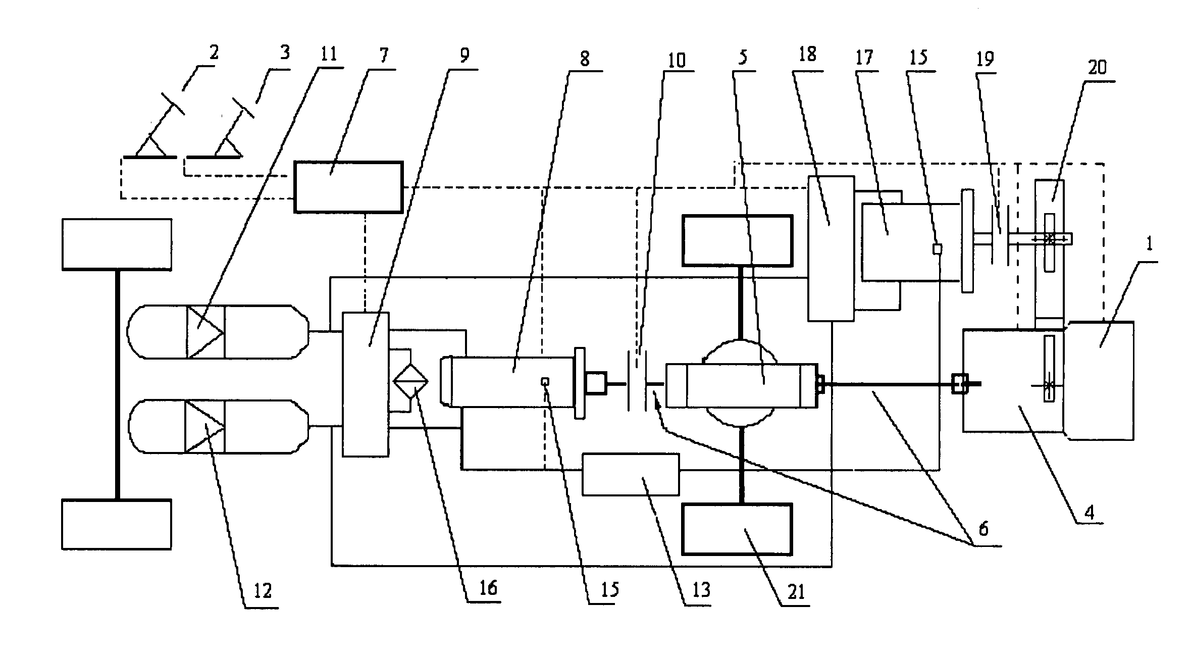
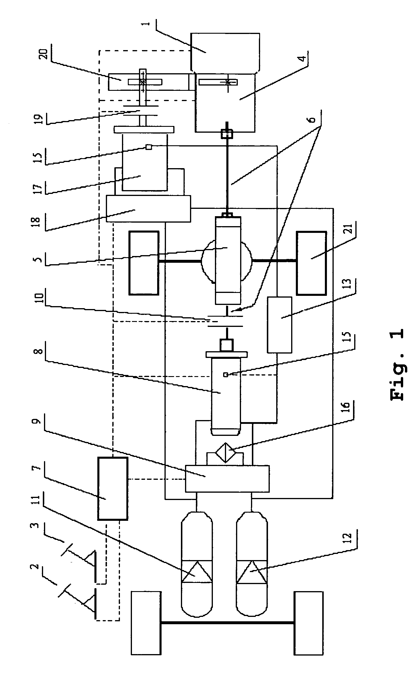
[0036]Referring to the FIG. 1, in the first embodiment, a power take-off apparatus is a power take-off 20. A power take-off gear is mounted at the end of a power output shaft of the gear-box 4, and a power take-off mechanical interface is disposed thereon. The interface is positioned at the end of a gear-box 4 adjacent to the engine 1. The power take-off 20 is mounted on the gear-box 4 through the interface. A power output shaft is mounted inside the power take-off 20. A gear and a second clutch are mounted on a power output shaft. The gear is engaged with a power take-off gear of a power input end of the gear-box 4, so that the power of engine is output and transferred.

second embodiment

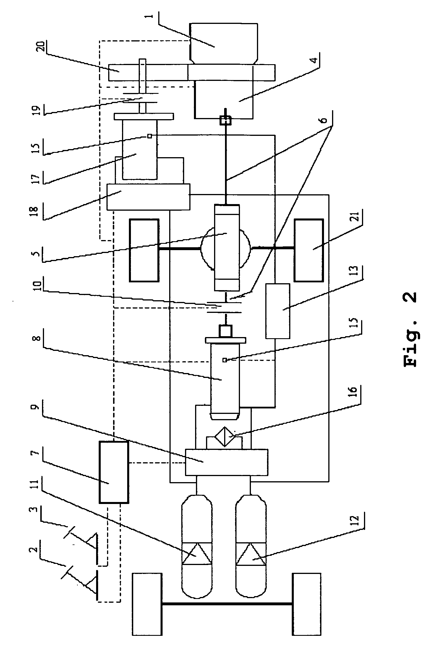
[0037]Referring to the FIG. 2, in the second embodiment, the power take-off apparatus is still a power take-off 20. The power take-off 20 is mounted at the end of the power output shaft of the engine 1. The gear-box 4 is connected to the other end of the power take-off 20. The gear and a second clutch 19 are mounted on the power output shaft of the power take-off 20. The gear is engaged with a power take-off gear of a power input end of the gear-box 4, so that the power of the engine is output and transferred.

third embodiment

[0038]Referring to the FIG. 3, in the third embodiment, the power take-off apparatus is an engine power output mechanism 14, which includes an engine crank output shaft, a strap wheel, a driving strap and a bracket. A strap wheel is mounted at an end of an engine crank output shaft which is connected with another strap wheel through a strap. Another strap wheel is mounted at an end of a bracket, while the second hydraulic pump / motor 17 is mounted at the other end of the bracket. The second clutch 19 is mounted in the middle of the bracket. When the clutch is disengaged, the strap wheel at an end of the engine crank output shaft drives the strap wheel on the bracket to spin. Only when the clutch is engaged, the engine drives the hydraulic pump / motor rotating, so that the power of the engine is output and transferred.

THE BASIC PRINCIPLE OF THE PRESENT INVENTION IS AS FOLLOWS

[0039]The operation process of the present invention is divided into four operation states, recovering hydraulic...


PUM


Abstract

The present invention relates to an engine hydraulic parallel series rear wheel drive hybrid vehicle, including a power transmission system for conventional vehicle, an electric control unit and a hydraulic auxiliary power transmission system, that is, braking energy regeneration auxiliary system and idling energy control system. A brake pedal and an accelerator pedal are connected with the hydraulic auxiliary power transmission system through the electronic control unit. The electronic control unit functions to realize harmonious control between the power transmission system and the hydraulic auxiliary transmission system. The electronic control unit receives electric signals given by the brake pedal, the accelerator pedal, the engine and the gear-box. After control strategic operation, the electronic control unit outputs an instruction signal of the auxiliary hydraulic power transmission system. The present invention can realize the recovering and releasing of hydraulic braking energy, utilizing of idling energy, and idling and shutting down of engine. The present invention has the advantages of higher efficiency of kinetic energy conversion, smaller noise, longer lifetime of engine, gas-saving, simpler structure and lower cost. The present invention is applicable to the reconfiguration of existing vehicle.

Description

FIELD OF THE INVENTION[0001]The present invention relates to an engine hydraulic parallel series rear wheel drive (RWD) hybrid vehicle, and more particularly, to a clean energy saving parallel series rear wheel drive hybrid vehicle equipped with an engine and a hydraulic accumulator, and more particularly, to a parallel series rear wheel drive hybrid vehicle having an engine as main power source and having stored and released hydraulic energy as an auxiliary power source.BACKGROUND OF THE INVENTION[0002]As the number of vehicles in China is increasing rapidly, a vehicle with high efficiency, excellent performance and simple structure will become popular. Because vehicles consume kinetic energy when braked and idled, and the kinetic energy can be converted into hydraulic energy by a hydraulic device and then stored in a hydraulic accumulator, in order to be provided to the vehicle as an auxiliary power source when the vehicle starts or accelerates, so as to realize the purpose of rec...

Claims


Application Information

Patent Timeline
IPC IPC(8): B60W10/24B60W20/00
CPCB60K6/12Y02T10/6282Y02T10/6208B60W20/00F02N7/00Y02T10/62B60K2006/126B60W2540/10B60W2540/12B60W20/20B60W10/18
Inventor GUO, HENGZHU, XIAOLINHAN, JUKUL
Owner BEIJING CHARGE BROAD EBERGY SAVING VEHICLE TECH
Why Eureka
Try Eureka