Heat Transfer Methods for Ocean Thermal Energy Conversion and Desalination

a technology of ocean thermal energy and transfer methods, applied in the direction of machines/engines, separation processes, barometric condensation, etc., to achieve the effect of eliminating the formation of mineral scal

Inactive Publication Date: 2009-03-26
PRUEITT MELVIN L
View PDF7 Cites 55 Cited by
  • Summary
  • Abstract
  • Description
  • Claims
  • Application Information

AI Technical Summary

Benefits of technology

[0007]The advantages of having the water evaporate from a flowing film of water rather than flashing the water to steam is that a water droplet collection system is not needed, and since there is no splashing of flashed water droplets, the formation of mineral scale is eliminated.
[0008]Rather than having a pre-deaerator to remove dissolved air in the incoming water, this system prevents the buildup of the air entrapped in the vapor flow and removes the air continually from the system.
[0011]It is therefore an object of the present invention to provide a method of transferring heat from warm ocean water to the boiler of an OTEC plant using water vapor as the heat transfer medium and doing it in such a manner that water droplet collection systems are not needed and mineral scale buildup is eliminated.

Problems solved by technology

Previous designs of OTEC plants with desalination used the warm water to produce the desalinated water on the boiler side of the system, but the cold side of the rankine cycle engine was not used for water production.

Method used


Image

  • Heat Transfer Methods for Ocean Thermal Energy Conversion and Desalination
  • Heat Transfer Methods for Ocean Thermal Energy Conversion and Desalination
  • Heat Transfer Methods for Ocean Thermal Energy Conversion and Desalination

Examples


Embodiment Construction

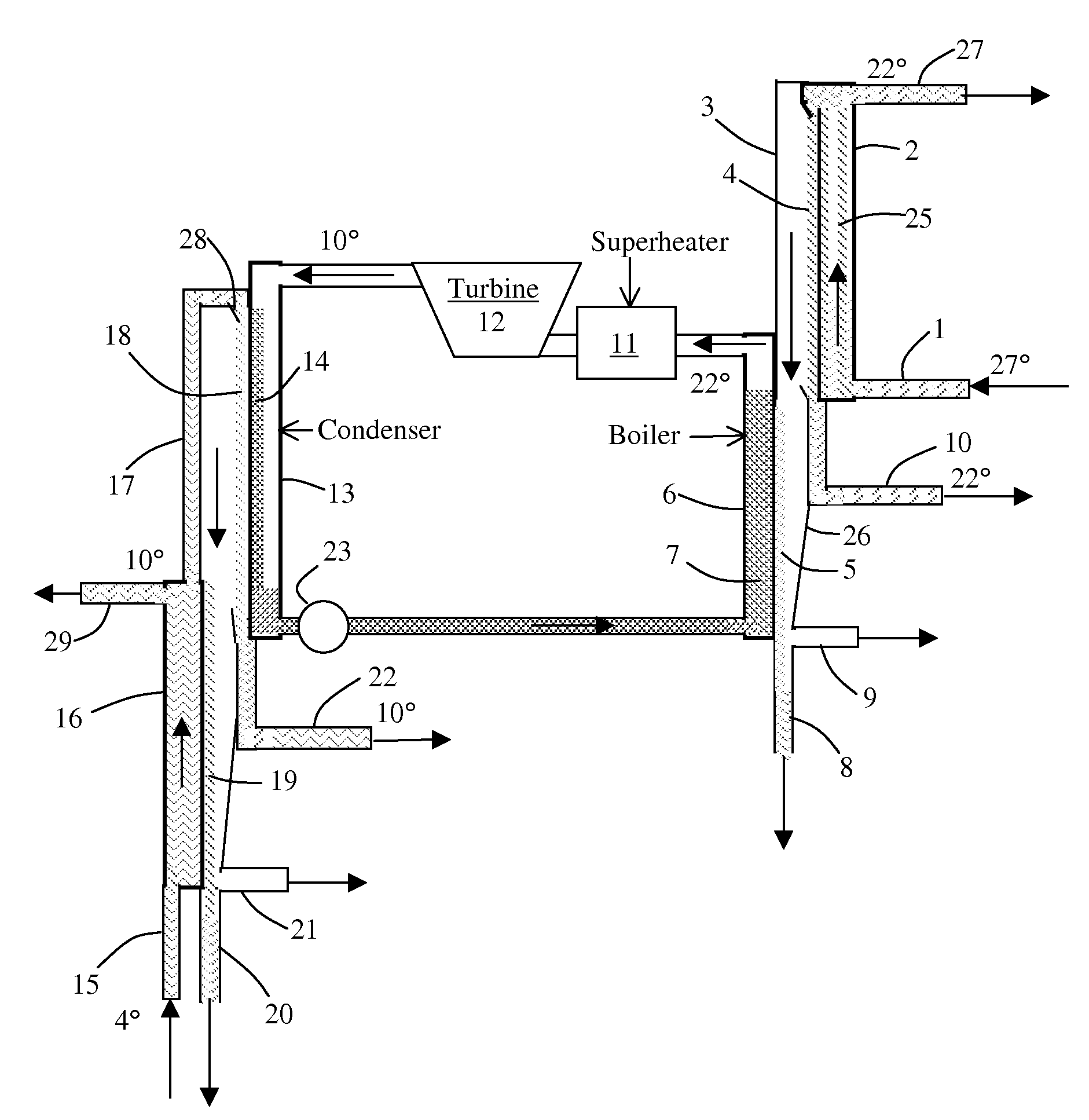
[0023]FIG. 1 shows schematically an embodiment of the present invention of an OTEC plant that uses water vapor as the heat transfer medium to move heat from the warm ocean water to the working fluid vapor, and uses water vapor as a heat transfer medium to transport heat from the condenser to the cold ocean water. It also shows the collection of fresh water from the warm and cold sides of the OTEC plant.

[0024]As the warm ocean water enters through pipe 1 to a heat exchanger 2, it provides heat through a heat exchanger wall to a film of seawater 4 that is flowing down the other side of the wall in an evacuated chamber 3. The warm water cools as it flows upward through the heat exchanger channel 25, because it is releasing heat to the water film 4. When it gets to the top of the channel 25, part of it then flows down as a film of water 4 on the right wall of the evacuated chamber 3. The rest of the water flows out the discharge pipe 27. Since the water flowing down as a film 4 has a te...


PUM

PropertyMeasurementUnit
temperatureaaaaaaaaaa
mechanical energyaaaaaaaaaa

Abstract

A means is provided to produce fresh water from seawater on both the boiler side and the condenser side of an OTEC power plant. Part of the warm ocean surface water is evaporated, and its vapor transfers heat to the working-fluid boiler as the vapor condenses. The condensation of the vapor provides fresh water. On the condenser side, the condensation of the working-fluid vapor from the turbine in the condenser releases heat that evaporates seawater that runs down the outside of the condenser surfaces. The vapor from the seawater is condensed by a heat exchanger that uses input from colder seawater. As the cold seawater accepts heat from the condensing vapor, it becomes slightly warmer and provides the source of seawater that accepts heat from the condenser. The condensing vapor on the heat exchanger becomes fresh water that is drawn out as potable water. To provide additional fresh water, a multi-stage desalination unit uses the warm water discharge and the cold-water discharge from the OTEC plant to provide a temperature gradient that causes evaporation and condensation in each stage of the unit.

Description

CROSS-REFERENCE TO RELATED APPLICATION[0001]This claims priority to and the benefit of Provisional U.S. Patent Application Ser. No. 60 / 827,881, filed Oct. 2, 2006, the entirety of which is hereby incorporated herein by reference.BACKGROUND OF THE INVENTION[0002]OTEC (Ocean Thermal Energy Conversion) plants have been used to produce electric power and to desalinate seawater. In one method, the warm water flashes to water vapor. In an open cycle system, the water vapor can drive a turbine and then is condensed to produce fresh water. For a closed cycle, the warm water is used to boil the working fluid in a heat exchanger or by allowing the warm water to flash to vapor, which then condenses on the boiler surfaces to release the heat of condensation of the water vapor, as presented in U.S. Pat. Nos. 5,513,494 and 4,324,983. The condensed water is fresh water that can be used by nearby communities. The working fluid is normally condensed in a heat exchanger by the flow of cold water thro...

Claims


Application Information

Patent Timeline
Patent Type & Authority Applications(United States)
IPC IPC(8): F03G7/05C02F1/16
CPCB01B1/005B01D1/0047B01D1/0088B01D1/22Y02E10/34B01D5/0048B01D5/006C02F1/046F03G7/05B01D5/0012Y02A20/00Y02A20/124Y02E10/30
Inventor PRUEITT, MELVIN L.
Owner PRUEITT MELVIN L
Why Eureka
Try Eureka