
Method and Device for Cleaning Circulation Water

a technology for cleaning devices and circulation water, which is applied in the direction of liquid fuel feeders, machines/engines, and the nature of treatment water, etc., can solve the problems of cumbersome operation and maintenance of cleaning devices, impaired cleaning performance of circulation water, and increased cost, so as to reduce the cost of operation and maintenance, the effect of efficient removal

Inactive Publication Date: 2008-11-06
KOGANEI
View PDF2 Cites 9 Cited by
  • Summary
  • Abstract
  • Description
  • Claims
  • Application Information

AI Technical Summary

Benefits of technology

[0016]However, during long-term operation of these types of cleaning devices, the amount of scale precipitated on the surface of the negative electrode plates is likely to grow over time, and as a result, electric current may be blocked and thus the cleaning performance of the circulation water will be impaired. Therefore, when scale is deposited and reaches or exceeds a certain level, service personnel have to detach the negative electrode plates from the cleaning device and physically remove the scale from the electrode plates. This poses a problem of cumbersome operation and maintenance of the cleaning device, along with increased cost.

Problems solved by technology

However, during long-term operation of these types of cleaning devices, the amount of scale precipitated on the surface of the negative electrode plates is likely to grow over time, and as a result, electric current may be blocked and thus the cleaning performance of the circulation water will be impaired.
This poses a problem of cumbersome operation and maintenance of the cleaning device, along with increased cost.
However, this cleaning device still requires that service personnel remove scale that has adhered to the surface of negative electrode plates by scraping it away, because scale that has firmly adhered to the surface of electrode plates cannot be completely peeled off and partly remains, the remaining scale would grow and then block the electric current, and as a consequence, circulation water cannot be cleaned.
Accordingly, this cleaning device also requires cumbersome operation and maintenance of the device, along with cost.
In addition, this type of cleaning device often uses electrode plates composed of materials, which comprise expensive rare metals including Pt, or are likely to be consumed rapidly such as Al, SUS and Fe.
Therefore, significant increased cost for constructing and maintaining the device remains.

Method used


Image

  • Method and Device for Cleaning Circulation Water
  • Method and Device for Cleaning Circulation Water
  • Method and Device for Cleaning Circulation Water

Examples


example 1

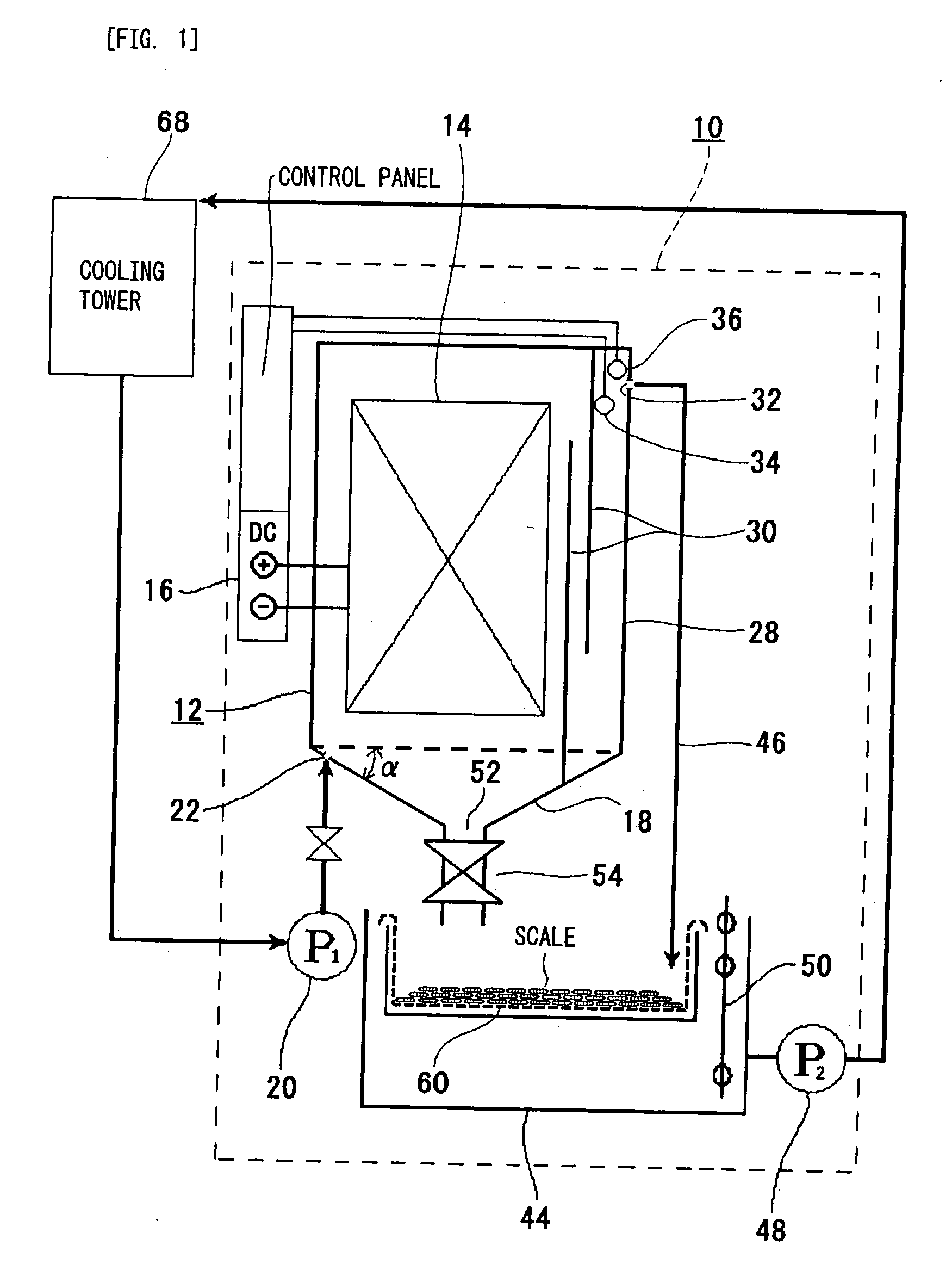
[0072]Circulation water in a cooling tower with a capacity of 120 refrigerating tons was withdrawn from a circulating channel, cleaned by passing through a device according to the present invention, and then brought back to the circulating channel.

[0073]The electrode plate unit 14 used in the device according to the present invention was comprised of seventy-two (72) titanium plates, having a width of 300 mm, a height of 600 mm, and a thickness of 1 mm. The thirty-six (36) plates were oriented so as to face the other thirty-six (36) titanium plates with a pitch of 24 mm between the plates. A constant current DC source was used as the DC source 16, in order to supply a constant current of six amperes to the electrode plate unit 14.

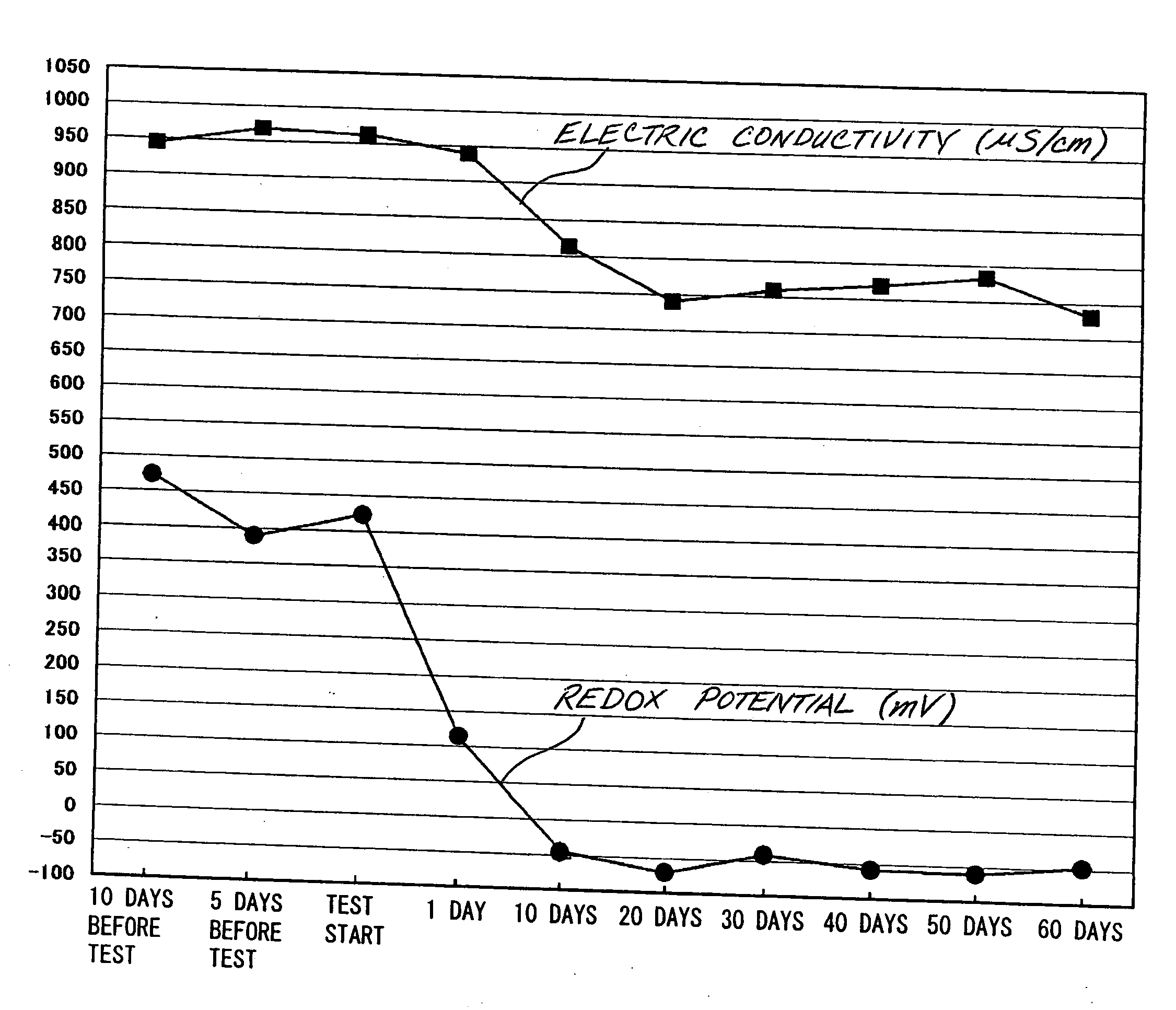
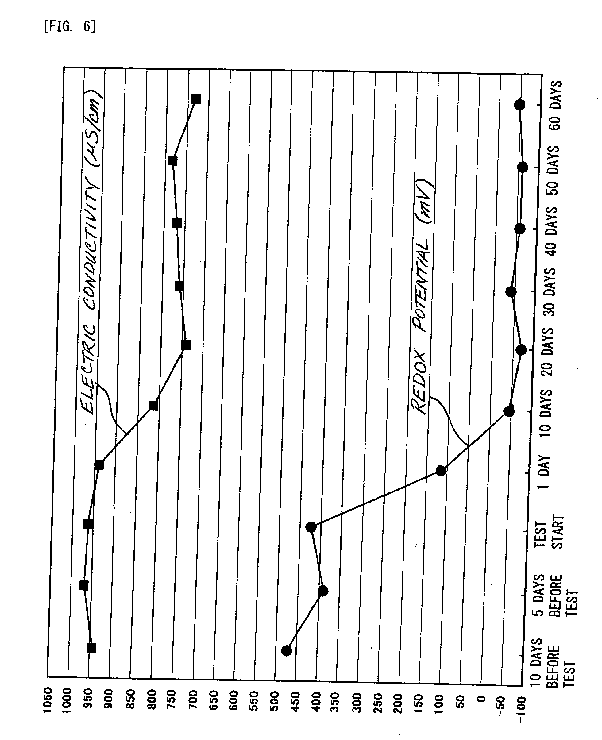
[0074]As shown in FIG. 5, voltage between the electrode plates was 0.5 V during an initial period, and derived from the constant current between the electrode plates supplied by the constant current DC source. However, the voltage gradually increased in con...

example 2

[0076]This experiment was performed in the same manner described in Example 1, except that the current density flowing between the electrode plates in the unit varied at three levels, i.e. 0.7 mA m2, 1.4 mA / m2 and 2.1 mA / m2. FIG. 7 shows the electric conductivity of the circulation water. This experiment demonstrates that higher current density decreases the electric conductivity of circulation water in a shorter period.

example 3

[0077]After a one-week of continuous operation under the conditions described in Example 1, the polarity was reversed and the operation was continued, and as a result, scale firmly adhered to the surface of the positive electrodes, which were negative electrodes before, was peeled off and deposited in the bottom of the electrolysis tank.

[0078]The operation was then continued for one more week under the same conditions, the scale was firmly adhered to the surface of the negative electrodes, as is the case with the initial operation. However, it was anticipated that further continuous operation would leave the scale firmly adhered to the negative electrodes, thereby making the recovery of the scale difficult, or reducing the efficiency of the adhesion of the scale due to the electric resistance. Therefore, the operation was continued by reversing the polarity alternately once every other week. As a result, scale adhered to the negative electrodes was efficiently peeled off, and then d...


PUM

PropertyMeasurementUnit
currentaaaaaaaaaa
electric conductivityaaaaaaaaaa
conductivityaaaaaaaaaa

Abstract

The object of the invention is to provide a method for cleaning circulation water, which reduces the cost of operation and maintenance as much as possible, without a cumbersome cleaning operation such as by detaching electrode plates from an electrolysis cleaning tank and removing scale from inside the tank, and to provide a device used in this method. Accordingly, the present invention provides a method for cleaning circulation water, comprising the steps of flowing circulation water to be cleaned between electrode plates placed in a face-to-face manner between one another; and applying DC voltage between the electrode plates, allowing one or more metal ions contained in the circulation water to be precipitated onto the negative electrode plates by electrolysis, to clean the circulation water, wherein the electrode plates used are made of titanium plates, and wherein a desired amount of current flows, while an anodized oxide coating formed on the surface of the positive electrode plates is compulsively subject to dielectric breakdown by increasing the voltage applied to the anodized oxide coating. FIG. 1 is a representative drawing.

Description

TECHNICAL FIELD[0001]The present invention relates to a device for cleaning circulation water, in order to electrically-remove scale contained in cooling water that is used in office facilities, manufacturing plants and the like, or used as circulation water between a condenser and a cooling tower in an air-conditioner.BACKGROUND ART[0002]FIG. 9 illustrates an air-conditioning system. As shown in this figure, an air-conditioner 64 comprises a compressor for compressing a gaseous refrigerant (not shown); a condenser 66 for cooling the compressed gaseous refrigerant by cooling water to convert into a liquid refrigerant; and an evaporator into which the liquid refrigerant flows after the pressure of the liquid refrigerant is reduced through an expansion valve (not shown).[0003]The condenser 66 is provided in a cooling tank 70, in order to cool refrigerant flowing inside the condenser 66. A cooling tower 68, which supplies cooling water to the cooling tank 70 through circulation of the ...

Claims


Application Information

Patent Timeline
Patent Type & Authority Applications(United States)
IPC IPC(8): C02F1/00
CPCC02F1/4602C02F1/4608C02F1/46109C02F2001/46119C02F2209/04C02F2103/023C02F2201/46135C02F2201/4614C02F2201/4617C02F2001/46133C02F1/461C02F1/50
Inventor TAGUCHI, YOSHIYUKINAKANO, TAKAYUKIKATO, MASAHITO
Owner KOGANEI
Learn More