Computed radiography system for mammography

a computed radiography and mammography technology, applied in the field of mammography, can solve the problems of limited clinical acceptance, high cost of dr detector replacement, and high cost of cr cassette replacement, so as to maximize x-ray absorption, improve the thickness of imaging plate, and facilitate the effect of dispersion

Inactive Publication Date: 2009-03-26
UCHICAGO ARGONNE LLC
View PDF13 Cites 20 Cited by
  • Summary
  • Abstract
  • Description
  • Claims
  • Application Information

AI Technical Summary

Benefits of technology

[0011]The first limitation described in the background section is overcome by the development of a storage phosphor material, which is transparent at the wavelength of the stimulating light. In a point scanned CR system using a transparent storage phosphor, the presampling Modulation Transfer Function (MTF) is determined by the size of the scanning laser beam, not the light scattering in the phosphor, and is thus decoupled from phosphor thickness. The imaging plate thickness can then be increased to maximize x-ray absorption for a given application, without suffering a resolution loss. This is a fundamental advantage of the novel TSP material.
[0012]The second limitation has been addressed on the materials side. ZBLAN storage glasses exhibit a useful dispersion in the behavior of optical turbidity (scattering) vs. wavelength, see U.S. patent application Ser. No. 11 / 267,056 filed Nov. 4, 2005 by Johnson et al., the entire disclosure of which is incorporated by reference. The optical scattering coefficient at the wavelength of the emitted (signal) light can be an order of magnitude higher than at the wavelength of the stimulating (scanning) light, due to scattering from the PSL-active BaCl2 crystallites in the ZBLAN glasses. This is highly desirable in a scanned CR system, because the collection efficiency (gain) for the emitted light is then much improved. In addition, a novel design for the light collector apparatus in the scanner for these materials, which improves the efficiency (gain) by yet another factor of two (as well as reducing “flare” and image artifacts and improving dynamic range) is disclosed.
[0013]Finally, the third limitation of current CR systems due to gain fluctuation noise is reduced. At least part of this noise is due to the depth variation of the signal light collection efficiency and scanning light-stimulation efficiency brought about by light scattering from phosphor particles dispersed in a binder. These effects are absent in a transparent storage phosphor system.

Problems solved by technology

DR systems, however, are much more expensive than CR, which has limited their clinical acceptance.
Furthermore, the replacement cost for a worn out or broken DR detector can be ten to one hundred times more expensive than replacing a CR cassette.
The image quality performance of CR has been limited in the past by three factors: (1) When the CR screen is made thick enough to achieve good x-ray absorption, the spatial resolution is disadvantaged compared to SF or DR, a particular problem for applications like mammography or bone radiography, (2) Because of limitations in screen conversion gain, collection efficiency, and detection efficiency, in a CR system that is not optimally designed, the number of detected electrons per absorbed x-ray (“gain”) can become low enough to become a secondary quantum sink, (3) CR systems have been observed to have rather high gain fluctuation noise, or “Swank noise”, compared to high quality SF or DR systems.

Method used


Image

  • Computed radiography system for mammography
  • Computed radiography system for mammography
  • Computed radiography system for mammography

Examples


first embodiment

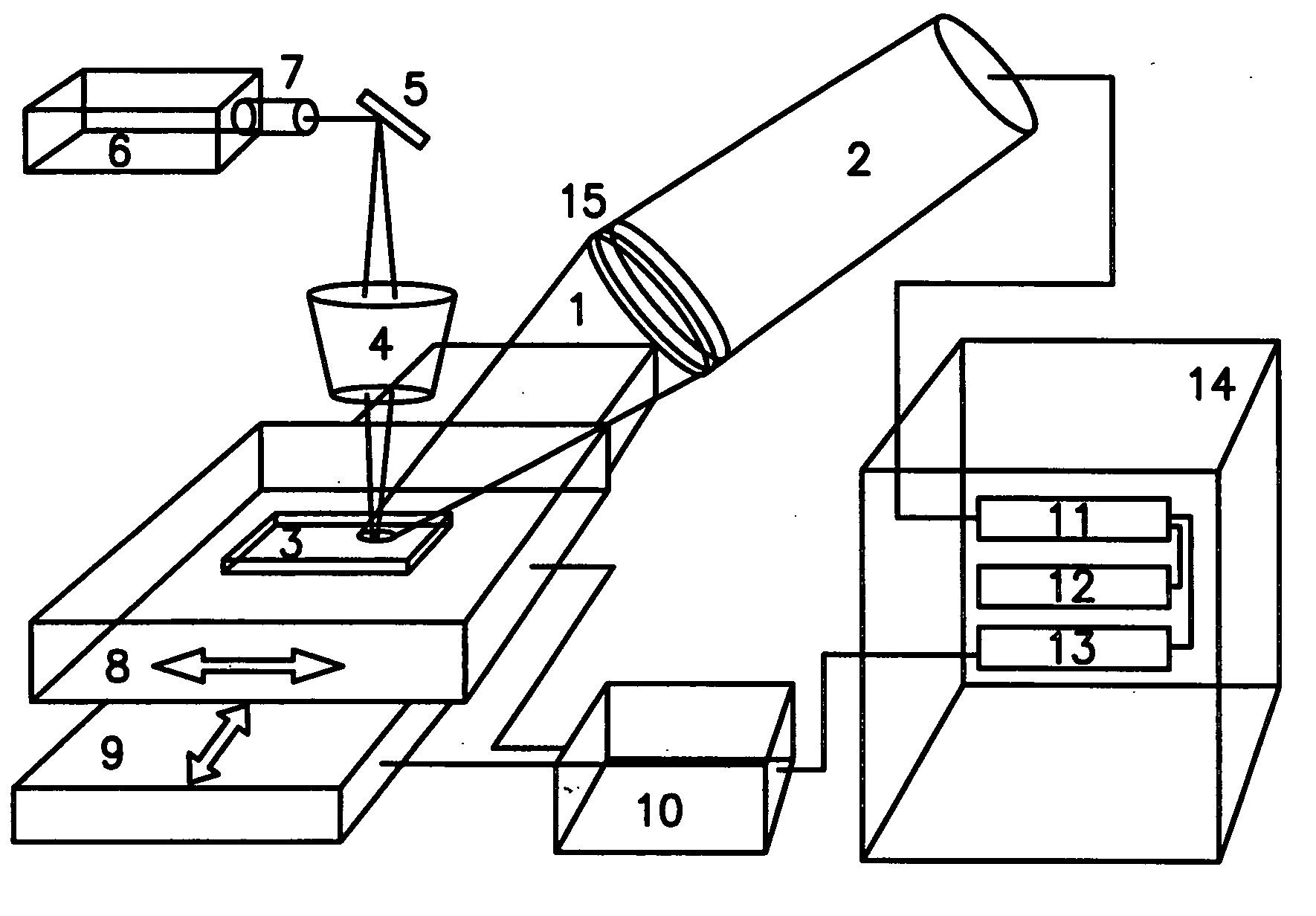
[0081]Referring to FIG. 11, the inventive system is shown. It is in the form of a portable, self-contained device, in a light-tight box shown in dotted line. Exposed photostimulable plates (3) are read out using the light from source (6), which may be a laser source. The stimulating light passes through a beam expander (7) and reflects from a folding mirror (5). The stimulating light beam is focused to the desired beam size at the imaging plate surface by the objective lens (4). The stimulating beam enters the imaging plate (3) in a direction perpendicular to the plate surface.

[0082]The stimulating beam, upon entering the imaging plate, stimulated stored electrons and holes to recombine, producing photostimulated luminescence light, which has a wavelength different from that of the stimulating slight. This light is collected by the light collector (1) and is directed towards a light detector (2). Before entering the detector (2), the light passes through an optical filter, such as t...

second embodiment

[0084]Referring to FIG. 12, the present invention is shown. It is in the form of a portable, self-contained device, in a light-tight box shown in dotted line. Exposed photostimulable plates (23) are read out using the light from source (27), which may be a laser source. The stimulating light passes through a beam expander (28) and reflects from galvanometer-driven rotating mirror (29), which comprises the light scanning element. The light beam reflected from the rotating mirror (29) then passes through the telecentric lens (24). The telecentric lens (24) must be equal or longer in length than the length of the scan line in the x direction. Lens (24) is telecentric in the image space, so that the principal rays emerge parallel to the optic axis, and thus enter the image plate (23) in a direction perpendicular to the plate surface. Lens (24) is further designed such that the stimulating beam is focused to a desired size at the plate surface, e.g. between 50 and 100 microns, for a 50 m...


PUM


Abstract

A computed radiography system including a stimulating light source such as a laser, a photostimulable glass imaging plate (PGIP) substantially transparent to the stimulating light positioned such that the stimulating light impinges the PGIP perpendicularly thereto producing photostimulated luminescence light (PLL), a light collector having a light reflecting inner surface proximate the PGIP for collecting PLL emitted from the PGIP and having a hole or slot therein for admitting stimulating light into the light collector and onto the PGIP. An optical filter in communication with the light collector for blocking stimulating light waves and passing PLL therethrough. A light detector receives PLL from the optical filter and the light collector, mechanism providing relative movement between the PGIP and the stimulating light source, and mechanism including an analog to digital converter for converting the collected and detected PLL to a diagnostic readout. The system is particularly useful in mammography.

Description

[0001]The United States Government has rights in this invention pursuant to Contract No. W-31-109-ENG-38 between the United States Government and The University of Chicago and / or pursuant to Contract No. DE-AC02-06CH11357 between the United States Government and UChicago Argonne, LLC representing Argonne National Laboratory.FIELD OF THE INVENTION[0002]This invention relates to a computed radiography (CR) system, components and method relating to mammography.BACKGROUND OF THE INVENTION[0003]In recent years computed radiography (CR) systems have been successful in replacing analog screen / film (SF) in many clinical settings. Such CR systems use photostimulable x-ray storage phosphor plates (for example, BaFBr:Eu2+), which are exposed in cassettes and then brought to an automated plate scanner, to read out the stored image information.[0004]CR systems bring numerous advantages such as electronic transmission and storage, image processing, and computer-aided diagnosis to clinical departm...

Claims


Application Information

Patent Timeline
Patent Type & Authority Applications(United States)
IPC IPC(8): G01T1/164A61B6/04
CPCG01T1/2012G01T1/2014
Inventor SCHWEIZER, STEFANJOHNSON, JACQUELINE A.LUBINSKY, ANTHONY R.
Owner UCHICAGO ARGONNE LLC
Why Eureka
Try Eureka