Fabrication of complex three-dimensional structures based on directed assembly of self-assembling materials on activated two-dimensional templates

a self-assembling, three-dimensional structure technology, applied in the field of nanofabrication techniques, can solve the problems of limited use of directed self-assembly, defects in patterns of approaches relying solely on copolymer self-assembly, and limitations of existing methods of using block copolymer materials

Active Publication Date: 2009-04-02
WISCONSIN ALUMNI RES FOUND
View PDF13 Cites 54 Cited by
  • Summary
  • Abstract
  • Description
  • Claims
  • Application Information

AI Technical Summary

Benefits of technology

[0007]The present invention meets these needs by providing methods of fabricating complex three-dimensional structures on patterned substrates, and related compositions. The methods involve depositing on the substrate a block copolymer material that is “mismatched” to the substrate pattern, and then ordering the material to form a complex three-dimensional structure. According to various embodiments the copolymer materials mismatches the substrate pattern in that the symmetry and / or length scale of its bulk morphology differs from that of the pattern. Mismatching the polymer morphology and the chemical patterns results in new and unique equilibrium structures. When ordered, a balance between the physics that determines the bulk block copolymer morphology and the physics that determines the substrate surface interfacial interactions results in a thermodynamically stable complex three-dimensional film that varies in a direction perpendicular to the substrate and has a morphology that differs from its bulk morphology.

Problems solved by technology

However, existing methods of using block copolymer material suffer from several limitations.
Approaches that rely solely on copolymer self-assembly suffer from defects in the patterns.
However, thus far the use of directed self-assembly has been limited to replicating the two-dimensional pattern of the substrate in the block copolymer film.

Method used


Image

  • Fabrication of complex three-dimensional structures based on directed assembly of self-assembling materials on activated two-dimensional templates
  • Fabrication of complex three-dimensional structures based on directed assembly of self-assembling materials on activated two-dimensional templates
  • Fabrication of complex three-dimensional structures based on directed assembly of self-assembling materials on activated two-dimensional templates

Examples


example 1

[0096]A ˜4 nm brush of polystyrene, PS, was grafted to a silicon substrate. A thin film of photoresist was subsequently deposited and patterned by four-beam extreme ultraviolet interference lithography. The resultant patterns in the photoresist layer consisted of square arrays of spots with nearest neighbor center-to-center distances of 71 nm≦Ls≦113 nm and a wide range of spot radii, R. The sample was then treated with an oxygen plasma such that PS brush regions not covered with photoresist were chemically modified to be oxygen-rich and highly polar. Removal of the remaining photoresist resulted in the desired chemically patterned substrate. A 44 nm film of a symmetric ternary blend, consisting of 60 wt. % poly(styrene-b-methyl methacrylate) (PS-b-PMMA, Mn=104 kg / mol, bulk lamellar period of 49 nm), 20 wt. % PS (40 kg / mol), and 20 wt. % poly(methyl methacrylate) (PMMA, 41 kg / mol), was deposited on the patterned substrate and annealed at 190° C. for 7 days. In thin films on uniform s...

example 2

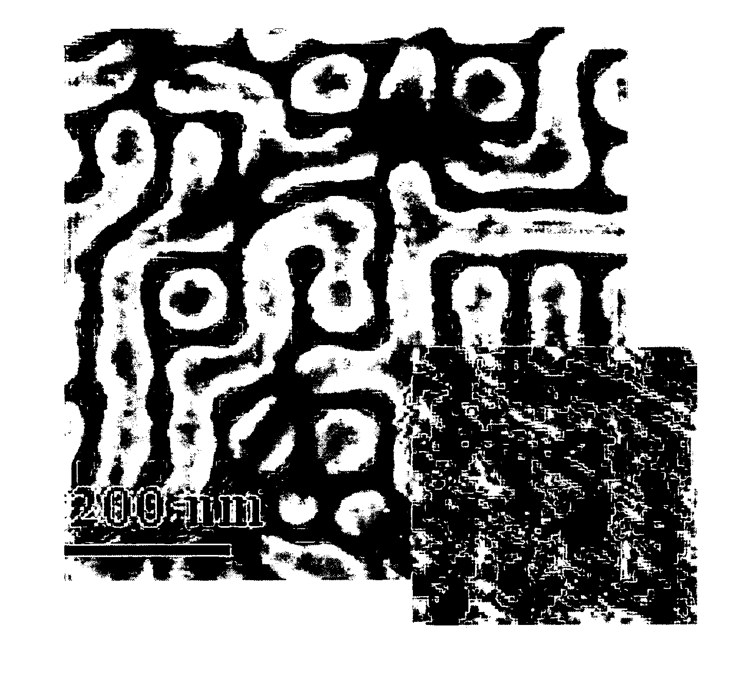
[0103]A patterned substrate was prepared having a Ls of 1.21L0 and R of 0.41L0 and a ternary PS-b-PMMA / PS / PMMA blend was deposited as described in Example 1. Thus, Ls was the same as for the film shown in FIG. 8A in Example 1, but the ratio R / Ls increased. The substrate was less preferential to PS on average than that in Example 1 (as the area of PMMA preferential wetting spots is increased). The amount of PS near the top surface of the film increased facilitating the formation of a bulk-like lamellar morphology. This can be seen in FIG. 9A, an SEM image of the surface of the film (with an AFM image inset to provide a more accurate depiction of the PS / PMMA dimensions), and FIG. 9B, which shows results of the SCMF simulation. Comparing FIGS. 9A and 9B with FIGS. 8A and 8B, it can be seen that for the film prepared in this Example, neighboring necks join into portions of standing lamellae that are connected to the QPL at the substrate and orient along the axis of the QPL. Also, by inc...

example 3

[0104]A patterned substrate was prepared having a Ls of 1.64L0 and R of 0.51L0 and a ternary PS-b-PMMA / PS / PMMA blend was deposited as described in Example 1. The resulting film is shown in FIGS. 10A and 10B, FIG. 10A being the SEM image, FIG. 10B the top view resulting from the SCMF simulation. The necks join into short portions of lamellae as in Example 2. Although the length scale, Ls, of the substrate pattern substantially exceeds the bulk period, L0, the substrate interactions force the formation of a QPL at the substrate. The width of the necks and short lamellar portions on the top, however, remains largely unaltered. The portions of lamellae either run along the diagonal or align parallel with the axis of the underlying square lattice. In the latter case, they bridge the PMMA-rich domains of the QPL. In response to the increase of the dimensions of the QPL, all necks now register with the bridge positions that are narrower than the interstitial ones. The bridge positions form...


PUM

PropertyMeasurementUnit
thickaaaaaaaaaa
lengthaaaaaaaaaa
lengthaaaaaaaaaa

Abstract

Methods of fabricating complex three-dimensional structures on patterned substrates and related compositions are provided. The methods involve depositing on the substrate a block copolymer material that is “mismatched” to the substrate pattern, and then ordering the material to form a complex three-dimensional structure. According to various embodiments, the copolymer material mismatches the substrate pattern in that the symmetry and / or length scale of its bulk morphology differs from that of the pattern. When ordered, a balance between the physics that determines the bulk block copolymer morphology and the physics that determines the substrate surface interfacial interactions results in a thermodynamically stable complex three-dimensional film that varies in a direction perpendicular to the substrate and has a morphology that differs from its bulk morphology.

Description

CROSS-REFERENCE TO RELATED APPLICATIONS[0001]This application claims priority under 35 USC §119(e) from U.S. Provisional Application No. 60 / 724,554, filed Oct. 6, 2005. This application also claims priority under 35 USC §119(e) from U.S. Provisional Application No. 60 / 761,863, filed Jan. 24, 2006. These applications are hereby incorporated by reference in their entireties and for all purposes.FIELD OF THE INVENTION[0002]The invention relates to methods of nanofabrication techniques. More specifically, the invention relates to patterning materials at the nanoscale level utilizing block copolymers.BACKGROUND OF THE INVENTION[0003]As the development of nanoscale mechanical, electrical, chemical and biological devices and systems increases, new processes and materials are needed to fabricate nanoscale devices and components. This is especially true as the scale of these structures decreases into the tens of nanometers. Block copolymer materials are useful in nanofabrication because they...

Claims


Application Information

Patent Timeline
Patent Type & Authority Applications(United States)
IPC IPC(8): B32B17/10B05D1/40
CPCB01D69/10B01D71/40B81C2201/0149Y10T428/269Y10T428/24612B32B3/30Y10T428/24322Y10T428/24331B81C1/00031B01D2323/225G03F7/70408B05D5/00Y10T428/24802B82Y30/00B01D71/80B32B17/10B32B3/00
Inventor NEALEY, PAUL FRANKLINSTOYKOVICH, MARK PETARDAOULAS, KONSTANTINOS C.MULLER, MARCUSDE PABLO, JUAN J.PARK, SANGMIN
Owner WISCONSIN ALUMNI RES FOUND
Why Eureka
Try Eureka