Patterned substrate with hydrophilic/hydrophobic contrast, and method of use

a contrast and hydrophilic technology, applied in the field of biomolecular arrays, can solve the problems of site directly affecting the reliability of resultant data, limited areal density, irregular shape and composition of spots (and thus reaction sites), etc., and achieves the density of potential reaction and/or absorption sites significantly, simple and effective methods

Inactive Publication Date: 2006-09-26
GLOBALFOUNDRIES INC
View PDF28 Cites 57 Cited by
  • Summary
  • Abstract
  • Description
  • Claims
  • Application Information

AI Technical Summary

Benefits of technology

[0010]A simple and effective method is disclosed for generating films that include 2-D (or 3-D, nanoporous) hydrophilic regions separated by hydrophobic regions. The hydrophilic regions have reaction sites suitable for receiving reagents and/or reactants (biological, biochemical, or otherwise) that can be detected when tagged with a compound that fluoresces in response to irradiation with light (UV light, for example). The emitted fluorescence can then be detecte

Problems solved by technology

The quality of the reaction sites directly affects the reliability of the resultant data.
With current microarray technology, which is dominated by the use of flat substrates (often glass microscope slides), areal density is limited.
A flat surface that promotes wetting, however, can lead to spots (and thus reaction sites) having irregular shapes and compositions.
Thus, flat surfaces are intrinsically limited by fluid-surface interactions

Method used


Image

  • Patterned substrate with hydrophilic/hydrophobic contrast, and method of use
  • Patterned substrate with hydrophilic/hydrophobic contrast, and method of use
  • Patterned substrate with hydrophilic/hydrophobic contrast, and method of use

Examples


example 1

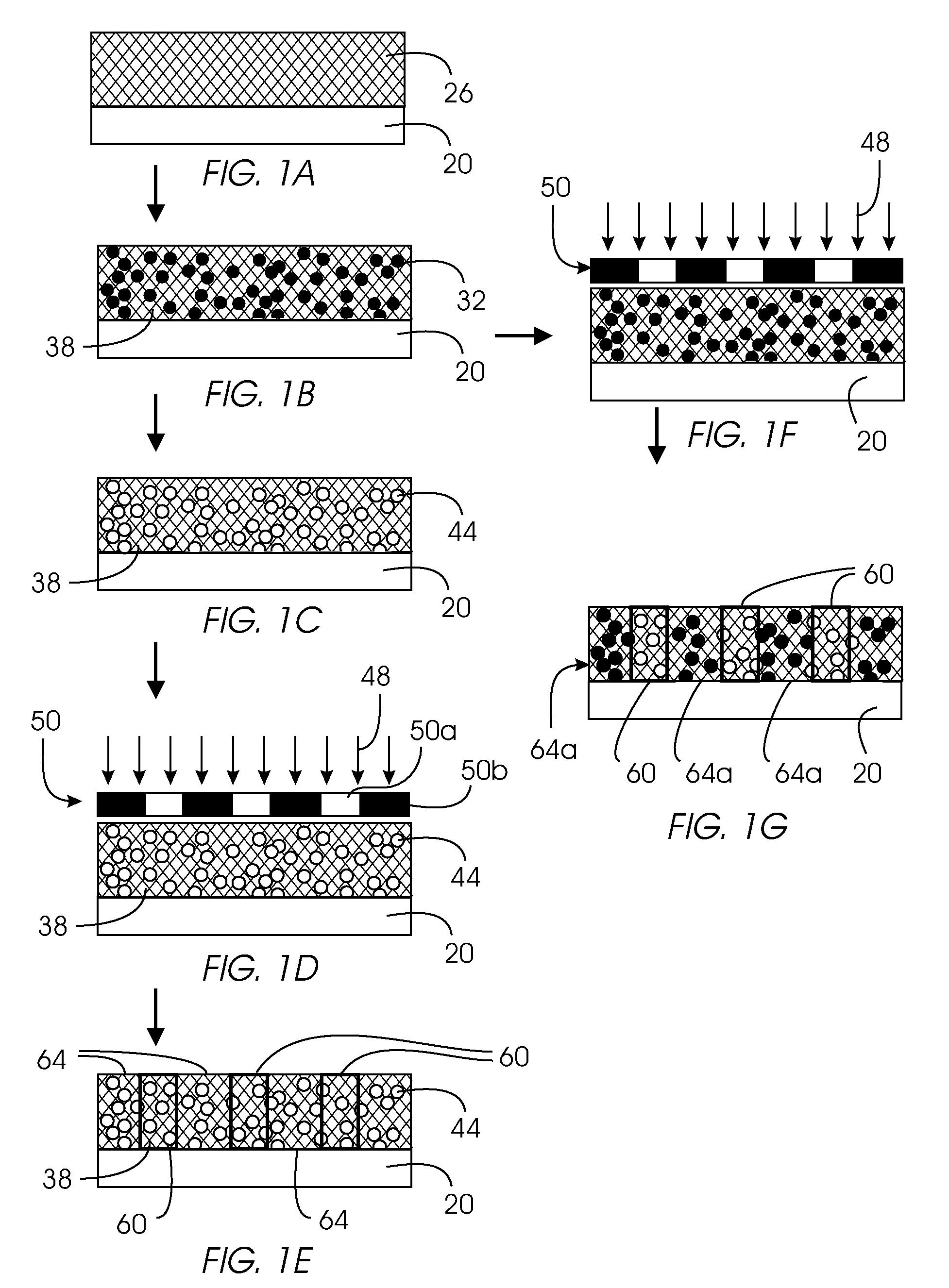
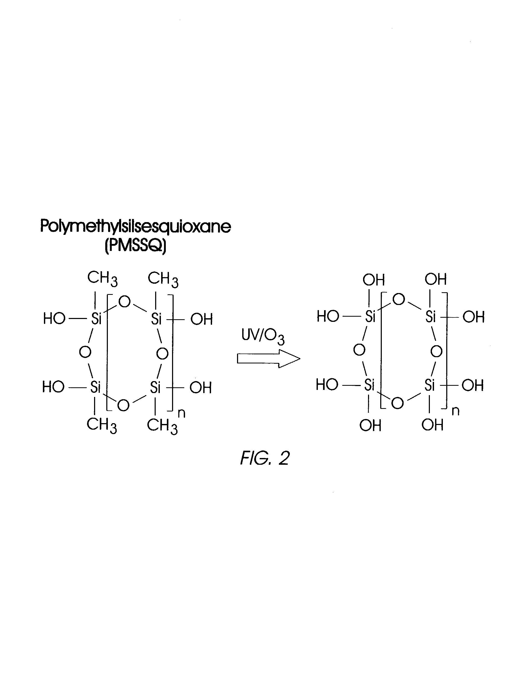
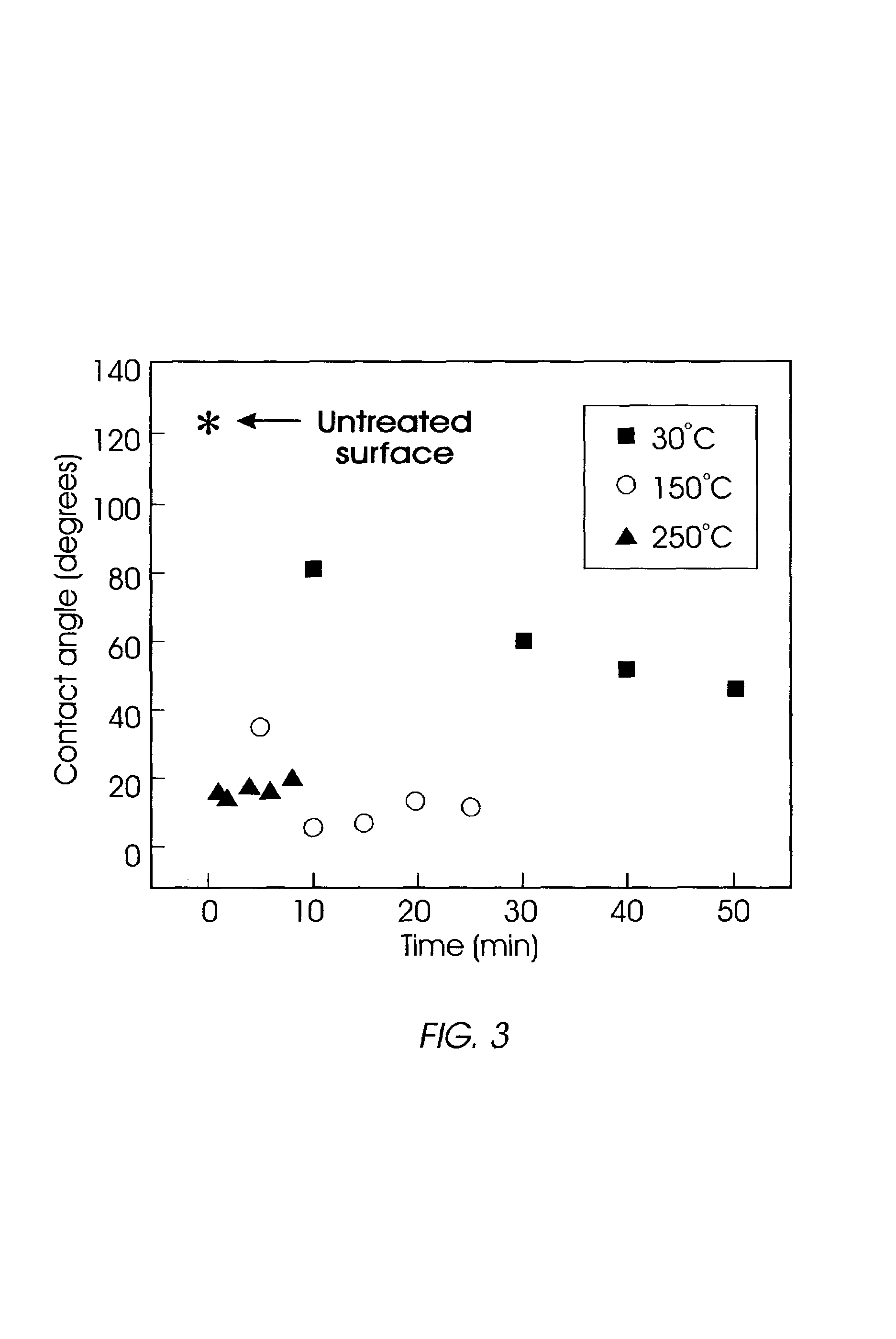
[0038]Static water contact angle measurements were made with an AST Video Contact Angle System 2500 XE to quantify the effect of UV / Ozone treatment (like that shown in FIG. 1D) on the surface properties of porous PMSSQ films (like that shown in FIG. 1C). FIG. 3 shows the contact angle as a function of treatment time for porous film produced from starting material of 80 wt. % porogen / 20 wt. % organosilicate. (Films of 10, 30, and 50 wt. % porogen were examined as well, and gave substantially similar results; films with a higher initial wt. % of porogen have greater porosity following decomposition of the porogen.) There is a rapid decrease in the contact angle over time, indicating that the surface is becoming more hydrophilic. This phenomenon is accelerated at higher temperatures, as a comparison between the data at 30° C. and 150° C. shows. A still more rapid decrease in the contact angle was observed at 250° C. The water contact angle decreases from more than 100 degrees initially...

example 2

[0039]By limiting UV exposure to those areas on a film corresponding to open areas within a metal mask (as shown by the mask of FIG. 1D, for example), hydrophilic patterns in a hydrophobic matrix can be obtained. In this case, only those areas on the film exposed to both UV and ozone become hydrophilic, while unexposed areas remain hydrophobic. Masks or schemes which create patterns of UV light are useful for this patterning. The result of such a patterning process is demonstrated in FIG. 4, which shows porous PMSSQ (on a 1″ silica wafer) on which water droplets are confined to ¼ inch diameter hydrophilic areas.

example 3

[0040]When hydrophilic areas are reduced in size to the point that they have a characteristic dimension (i.e., an approximate width or length) of 250 microns or less, the surface tension of water prevents the formation of well-defined drops (like those shown in FIG. 4), so that only wavy shapes at the water / surface / air contact line are evident, indicating that probe molecules in aqueous solution can be confined to the hydrophilic patterned areas. Indeed, the surface hydroxyl groups generated by UV / Ozone treatment are themselves useful for chemical reactions for bonding probe molecules covalently.

[0041]To demonstrate that a higher number density of —OH groups is available within a i) UV / ozone treated porous organosilicate medium than either ii) a flat silica substrate that was not treated with UV / ozone or iii) non-porous MSSQ treated with UV / ozone, a fluorescent dye was used. Specifically, the linker 3-bis(2-hydroxyethyl)amino propyl triethoxysilane was attached to —OH groups on repr...


PUM

PropertyMeasurementUnit
Lengthaaaaaaaaaa
Lengthaaaaaaaaaa
Polarityaaaaaaaaaa

Abstract

A gas phase species (such as ozone, H2O2, or N2O) is photodissociated with ultraviolet light into a reactive species that is patternwise directed (e.g., through a mask) onto a surface of a material, such as an organosilicate. The reactive species reacts with the material to form a polar oxidation product such as —OH, thereby resulting in discrete hydrophilic regions separated from each other by hydrophobic regions. The degree of hydrophilicity of the discrete regions may be tailored by controlling the concentration of the reactive species, the ultraviolet light intensity, the temperature to which the material is heated, and exposure time. End products made with the methods are suitable for use in a biomolecular array.

Description

TECHNICAL FIELD[0001]The invention relates to a process of forming arrays patterned into regions of varying hydrophilicity, especially biomolecular arrays.BACKGROUND[0002]Biomolecular arrays have quickly developed into an important tool in life science research. Microarrays, or densely-packed, ordered arrangements of miniature reaction sites on a suitable substrate, enable the rapid evaluation of complex biomolecular interactions. Because of their high-throughput characteristics and low-volume reagent and sample requirements, microarrays are now commonly used in gene expression studies, and they are finding their way into significant emerging areas such as proteomics and diagnostics.[0003]The reaction sites of the array can be produced by transferring to the substrate droplets containing biological or biochemical material. A variety of techniques can be used, including contact spotting, non-contact spotting, and dispensing. With contact spotting, a fluid bearing pin leaves a drop on...

Claims


Application Information

Patent Timeline
IPC IPC(8): C08F2/46C08J7/12C08J7/18G03C1/73
CPCG03C1/731Y10T428/249961
Inventor KIM, HO-CHEOLMILLER, ROBERT DENNIS
Owner GLOBALFOUNDRIES INC
Why Eureka
Try Eureka