
Heat generation mechanism-provided secondary battery

a secondary battery and heat generation mechanism technology, applied in secondary cell servicing/maintenance, cell components, electrochemical generators, etc., can solve the problems of high temperature ignition risk, complex devices, high battery properties, etc., and achieve good safety, good discharge capacity, and poor battery properties

Inactive Publication Date: 2009-04-02
OHARA
View PDF4 Cites 56 Cited by
  • Summary
  • Abstract
  • Description
  • Claims
  • Application Information

AI Technical Summary

Benefits of technology

[0014]Under the foregoing circumstances, the invention has been made, and its object is to enable even a secondary battery which is poor in battery properties at a low temperature to realize a sufficient discharge capacity. In particular, in a solid based electrolyte battery which is large in an advantage on safety, the invention is able to make both safety and battery performance compatible with each other by improving the poor low-temperature properties.
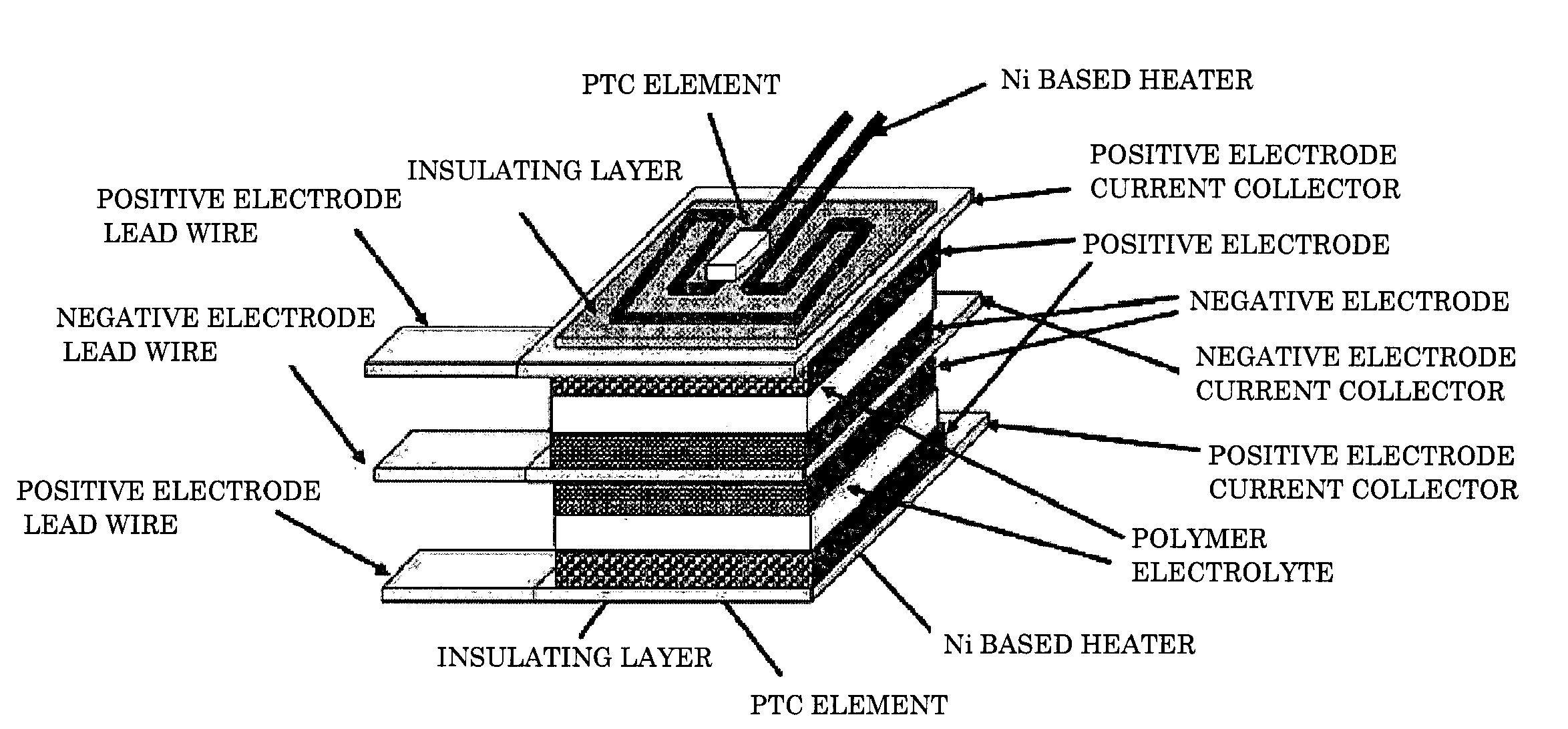
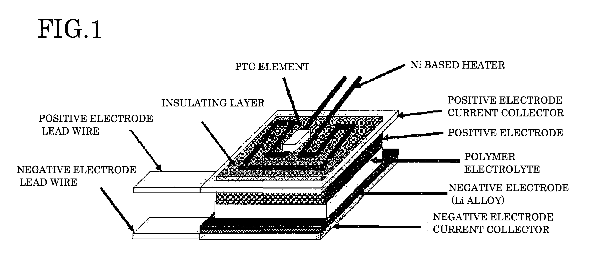
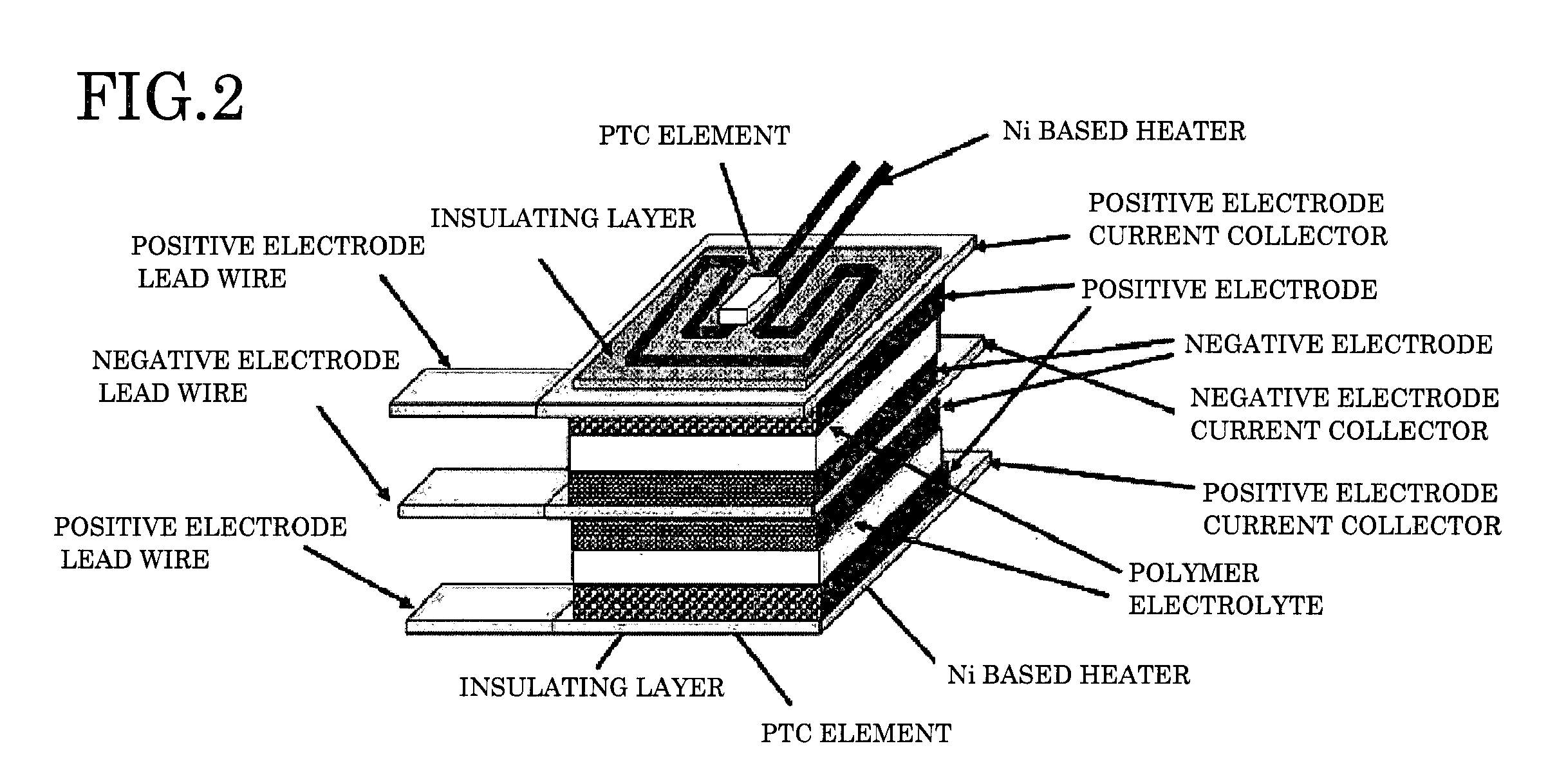
[0015]The present inventor has found out that by configuring a cell of a secondary battery in a sheet form and providing the cell with a heat generation unit by carrying a current, a sufficient battery performance can be brought even in a battery with a low discharge performance at a low temperature.

Problems solved by technology

As compared with automobiles with only an internal combustion engine, the hybrid vehicle contains a number of parts including a motor and a battery and is complicated with regard to devices.
However, due to an environmental problem or following an increase of needs to realize a long traveling distance by only a battery, an electric power source for hybrid vehicle having an energy density per unit volume or weight is demanded.
However, in general, the lithium ion battery uses an organic solvent, and therefore, it is risky in ignition at a high temperature.
For example, in the case where the lithium ion battery is used as a motor electric power source of automobile, the deterioration of a positive electrode material or the decomposition of an electrolytic liquid is extreme in the environment where the temperature in the vehicle is high, for example, a high outside air temperature or direct sunlight, and following this, the battery causes thermal runaway, whereby the risk of occurrence of liquid leakage or ignition becomes high.
Also, in the case where the battery is burst due to an accident or the like, the electrolytic liquid leaks, and the risk of occurrence of ignition or explosion is generated.
However, the electrolyte of a general polymer battery is a gel prepared by containing an organic electrolytic liquid in a polymer material, and the polymer battery is not substantially different from the lithium secondary battery in the point that an organic electrolyte is contained.
However, in the case where the battery itself is overheated, the risk of occurrence of ignition of the organic electrolytic liquid to be contained in the electrolyte is unavoidable.
However, the foregoing polymer electrolyte and solid electrolyte involve a problem that in the case where the temperature is low, the ionic conductivity becomes noticeably low.
For example, in the environment where the temperature is low as −20 to −30° C., an output of the battery is not substantially obtainable.
In particular, in the case where the use as a motor electric power source of an automobile which should be supposed to be used in a cold district is considered, a sufficient output cannot be exhibited due to its low ionic conductivity in the foregoing low-temperature environment, and the automobile undergoes the generation of electricity and traveling substantially only by an internal combustion engine.
In that case, in view of the matter that heavy battery and motor are mounted, the fuel consumption is rather deteriorated as compared with that in usual automobiles not mounted with a hybrid system.
Because of such poor low-temperature properties, a polymer battery or a solid type battery using a solid electrolyte has not been sufficiently put into practical use yet.

Method used


Image

  • Heat generation mechanism-provided secondary battery
  • Heat generation mechanism-provided secondary battery
  • Heat generation mechanism-provided secondary battery

Examples


example 1

[0048]An organic electrolyte liquid-free polymer lithium ion secondary battery having an Ni alloy-made heater provided on a current collector was prepared (this polymer lithium ion secondary battery will be hereinafter referred to as “invention battery 1”). Commercially available LiCoO2 was used as a positive electrode material; an Li metal alloy foil was used as a negative electrode; and a polymer electrolyte prepared by adding, as an Li supporting salt, LiTFSI (lithium trifluoromethanesulfonylimide) to a copolymer of polyethylene and polypropylene was used as an electrolyte.

[0049]On an Al foil as a positive electrode current collector, a slurry of a positive electrode material prepared using a solvent was coated and dried to form a positive electrode layer. On the positive electrode layer, a slurry prepared by adding LiTFSI (lithium trifluoromethanesulfonylimide) to a copolymer of polyethylene and polypropylene by using a solvent was coated and dried to form an electrolyte layer. ...

example 2

[0053]An organic electrolyte liquid-free lithium ion secondary battery having a ceramic heater provided on a current collector was prepared (this lithium ion secondary battery will be hereinafter referred to as “invention battery 2”). Commercially available LiCoO2 as an active material was used as a positive electrode material; Li4Ti5O12 as an active material was used as a negative electrode material; and an organic-inorganic composite electrolyte prepared by mixing a polymer electrolyte prepared by adding, as an Li supporting salt, LiTFSI (lithium trifluoromethanesulfonylimide) to a copolymer of polyethylene and polypropylene with an inorganic solid electrolyte powder was used as an electrolyte. A glass ceramic powder in which an LiTi2(PO4)3 solid solution having a crystal structure of an NASICON type was deposited in a main crystal phase was used as the inorganic solid electrolyte.

[0054]On an Al foil as a positive electrode current collector, a slurry of a positive electrode mater...

example 3

[0058]A solid electrolyte type lithium ion secondary battery having a PTC thermistor provided on a current collector was prepared (this lithium ion secondary battery will be hereinafter referred to as “invention battery 3”). A glass ceramic containing Li1+x+y(Al, Ga)x(Ti, Ge)2−xSiyP3−yO12 in a main crystal phase was used as an electrolyte. The glass ceramic was prepared by dissolving oxide raw materials in a Pt pot, casting the thus dissolved molten glass into a stainless steel-made mold and quenching it to obtain glass, followed by again heating the glass for crystallization. The glass ceramic had a size of 50 mm in square, and the both surfaces thereof were ground and polished to process into a disc, thereby forming a solid electrolyte. Commercially available LiCoO2 as an active material was used as a positive electrode material; Li4Ti5O12 as an active material was used as a negative electrode material; a PVdF resin was used as a binder; a glass ceramic powder in which an LiTi2(PO...


PUM


Abstract

In a secondary battery which is poor in battery properties at a low temperature, by making the temperature of the secondary battery in a state of the largest discharge capacity, a secondary battery which can be used under a condition such as a cold district is obtained. A cell of the battery is configured in a sheet form, and the cell is provided with a heat generation unit capable of generating heat by carrying a current. According to this configuration, the battery can be used at a temperature with good capacity properties regardless of the ambient temperature environment. In particular, in an organic electrolytic liquid-free polymer electrolyte or solid electrolyte-containing lithium ion secondary battery which is high in energy density but poor in battery properties at a low temperature, a sufficient battery performance can be brought out regardless of the temperature environment.

Description

CROSS REFERENCES TO RELATED APPLICATIONS[0001]The present invention contains subject matter related to Japanese Patent Application No. 2007-257534 filed with the Japan Patent Office on Oct. 1, 2007, the entire contents of which being incorporated herein by reference.BACKGROUND OF THE INVENTION[0002]1. Field of the Invention[0003]The present invention mainly relates to a rechargeable battery provided with a heating function.[0004]2. Description of the Related Art[0005]In recent years, from the viewpoints of reduction of global greenhouse gas and energy conservation, a hybrid vehicle mounted with both an engine using gasoline as a fuel and an electric motor is watched as a vehicle which is low in an amount of an exhaust gas and good in fuel consumption. As compared with automobiles with only an internal combustion engine, the hybrid vehicle contains a number of parts including a motor and a battery and is complicated with regard to devices. However, its development and improvement are...

Claims


Application Information

Patent Timeline
IPC IPC(8): H01M10/50H01M10/615H01M10/052H01M10/0562H01M10/0565H01M10/48H01M10/60H01M10/625H01M10/637H01M10/6571H01M10/6572H01M50/569
CPCH01M10/425H01M10/486H01M10/5006H01M10/5016Y02E60/122H01M10/5032H01M10/5083H01M16/003H01M10/5026H01M10/625H01M10/615H01M10/637H01M10/647H01M10/6571Y02E60/50Y02E60/10H01M50/569
Inventor INDA, YASUSHI
Owner OHARA
Learn More