
Flattening method and flattening apparatus

a flattening apparatus and flattening method technology, applied in the direction of lapping tools, semiconductor devices, decorative arts, etc., can solve the problems of high-throughput processing difficulty with the care method, significantly low processing rate as compared to grinding, cmp, etc., and achieve high precision, sufficient processing rate, and enhance the effect of flatness

Active Publication Date: 2009-04-16
EBARA CORP
View PDF18 Cites 52 Cited by
  • Summary
  • Abstract
  • Description
  • Claims
  • Application Information

AI Technical Summary

Benefits of technology

[0006]The CARE method, which carries out removal processing (etching) of a surface of a workpiece, e.g., composed of SiC or GaN, has the advantageous features that it can process a surface (surface to be processed) of a workpiece with higher precision as compared to conventional processing methods such as CMP and can obtain a processed surface having high flatness and, in addition, can process the workpiece without leaving damage in the processed surface. However, the CARE method, in which removal processing (etching) of a surface of a workpiece progresses through dissolution in a processing solution of a halogen compound produced by chemical reaction between a halogen radical and a surface atom of the workpiece, has the drawback that the processing rate is significantly low as compared to grinding, CMP, etc. which are commonly used in the manufacturing of a semiconductor device. Thus, high-throughput processing is difficult with the CARE method.
[0007]The present invention has been made in view of the above situation in the related art. It is therefore an object of the present invention to provide a flattening method and a flattening apparatus which, by utilizing the advantages of the CARE method and making up for the disadvantages, can perform removal processing of a surface of a workpiece at a sufficient processing rate and can provide a processed surface having enhanced flatness without leaving damage in the processed surface.

Problems solved by technology

However, the CARE method, in which removal processing (etching) of a surface of a workpiece progresses through dissolution in a processing solution of a halogen compound produced by chemical reaction between a halogen radical and a surface atom of the workpiece, has the drawback that the processing rate is significantly low as compared to grinding, CMP, etc. which are commonly used in the manufacturing of a semiconductor device.
Thus, high-throughput processing is difficult with the CARE method.

Method used


Image

  • Flattening method and flattening apparatus
  • Flattening method and flattening apparatus
  • Flattening method and flattening apparatus

Examples


Embodiment Construction

[0053]Preferred embodiments of the present invention will now be described with reference to the drawings. The following description illustrates the case of using hydrofluoric acid (HF) as a processing solution and platinum as a catalyst, and processing and removing a surface (surface to be processed) of a substrate, such as an SiC wafer, into a desired flatness.

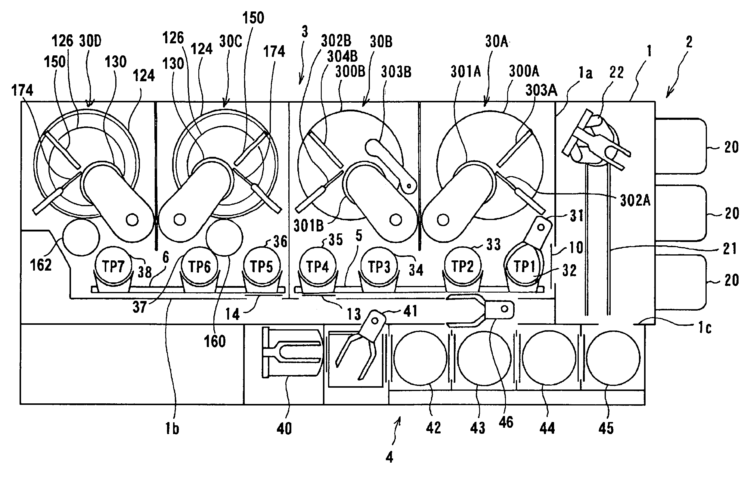
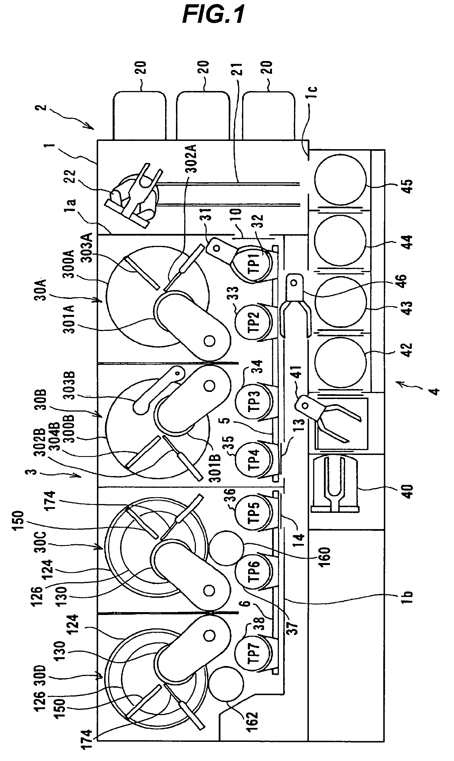
[0054]FIG. 1 is a plan view showing the overall construction of a flattening apparatus according to an embodiment of the present invention. As shown in FIG. 1, the flattening apparatus of this embodiment includes a generally rectangular housing 1 whose interior is divided by partition walls 1a, 1b, 1c into a loading / unloading section 2, a surface removal processing section 3 and a cleaning section 4. The loading / unloading section 2, the surface removal processing section 3 and the cleaning section 4 are independently fabricated and independently ventilated.

[0055]The loading / unloading section 2 includes at least two (three in...


PUM

PropertyMeasurementUnit
widthaaaaaaaaaa
groove depthaaaaaaaaaa

Abstract

A flattening method, by utilizing the advantages of the CARE method and making up for the disadvantages, can perform removal processing of a surface of a workpiece at a sufficient processing rate and can provide a processed surface having enhanced flatness without leaving damage in the processed surface. A flattening method comprises at least two surface removal steps and at least two cleaning steps, the final surface removal step being a catalyst-referred etching step comprising immersing a workpiece in a processing solution containing at least one of hydrohalic acid, hydrogen peroxide water and ozone water, and bringing a surface of a catalyst platen into contact with or close proximity to a surface to be processed of the workpiece to process the surface, said catalyst platen having in a surface a catalyst selected from the group consisting of platinum, gold, a ceramic solid catalyst, a transition metal, glass, and an acidic or basic solid catalyst.

Description

BACKGROUND OF THE INVENTION[0001]1. Field of the Invention[0002]The present invention relates to a flattening method and a flattening apparatus, and more particularly to a flattening method and a flattening apparatus for flatly processing a surface (surface to be processed) of a workpiece, such as a simple substrate consisting of SiC or GaN, a bonded substrate (epitaxial substrate) having a layer of SiC or GaN, or a substrate for use in MEMS (micro electro mechanical system).[0003]2. Description of the Related Art[0004]With the recent progress toward higher integration of semiconductor devices, the circuit interconnects are becoming finer and the distance between adjacent interconnects is becoming smaller. Especially when forming a circuit pattern by optical lithography with a line width of not more than 0.5 μm, a stepper requires a high flatness of imaging surface because of the small depth of focus. A CMP apparatus for carrying out chemical mechanical polishing (CMP) is known as a...

Claims


Application Information

Patent Timeline
Patent Type & Authority Applications(United States)
IPC IPC(8): B44C1/22C23F1/08
CPCH01L21/02019H01L21/30612H01L21/67207H01L21/67075H01L29/1608B24B37/32H01L21/67219B24B37/11H01L21/7684H01L21/3212H01L21/32115H01L21/30625
Inventor YAMAUCHI, KAZUTOSANO, YASUHISAHARA, HIDEYUKIMURATA, JUNJIYAGI, KEITA
Owner EBARA CORP
Learn More