Method of manufacturing semiconductor device, method of manufacturing display apparatus, apparatus of manufacturing semiconductor device, and display apparatus

a display apparatus and semiconductor technology, applied in the field of manufacturing semiconductor devices, can solve the problems of irradiation optical systems that may tilt accidentally, display unevenness in display apparatuses, and visual recognition of characteristic differences of tft, so as to reduce the characteristic variation of semiconductor devices formed over the semiconductor film, the difference between crystallinity in the forward path and crystallinity in the backward path is reliably suppressed, and the output is higher.

Inactive Publication Date: 2009-04-16
SONY CORP
View PDF2 Cites 10 Cited by
  • Summary
  • Abstract
  • Description
  • Claims
  • Application Information

AI Technical Summary

Benefits of technology

[0013]It is therefore desirable to provide a method of manufacturing a semiconductor device realizing higher throughput by making a laser beam reciprocate while reliably suppressing the difference between crystallinity in a forward path and that in a backward path, a method of manufacturing a display apparatus, an apparatus of manufacturing a semiconductor device, and a display apparatus realizing suppressed display unevenness and higher display quality by using the methods and the apparatus.
[0020]In the first or second apparatus of manufacturing the semiconductor device of the embodiment of the present invention, the structure to be irradiated including the semiconductor film formed over the substrate is irradiated with a laser beam, thereby modifying the semiconductor film. In the operation, the laser beam and the substrate are moved by the moving means relatively in the first direction and the second direction which is opposite to the first direction, so that the throughput becomes higher. By the modulating means, a change in the optical characteristic between the area irradiated with the laser beam and the area which is not irradiated with the laser beam in the substrate, or the optical characteristic of the irradiated area is measured in each of the first and second directions. The irradiation power of the laser power or the relative speeds of the laser beam and the substrate are modulated so that the difference between a measurement result in the first direction and a measurement result in the second direction lies in a predetermined range. Therefore, the difference between crystallinity in the forward path and crystallinity in the backward path is reliably suppressed in the modified semiconductor film, and the characteristic variation in the semiconductor device formed over the semiconductor film is reduced.
[0021]Each of the first and second display apparatuses of the present invention has the semiconductor device formed by the first or second method of manufacturing the semiconductor device. Thus, the characteristic difference between the semiconductor devices is reduced, and display unevenness is suppressed.
[0022]In the first method of manufacturing the semiconductor device, the first method of manufacturing the display apparatus, and the first apparatus of manufacturing the semiconductor device of the embodiment of the present invention, the laser beam and the substrate are moved relative to each other in a first direction and a second direction which is opposite to the first direction, a change in an optical characteristic between an area irradiated with the laser beam and an area which is not irradiated with the laser beam in the substrate or an optical characteristic of the irradiated area is measured in each of the first and second directions. Irradiation power of the laser beam is modulated so that the difference between a measurement result in the first direction and a measurement result in the second direction lies in a predetermined range. Further, in the second method of manufacturing the semiconductor device, the second method of manufacturing the display apparatus, and the second apparatus of manufacturing the semiconductor device of the embodiment of the present invention, similarly, the relative speeds of the laser beam and the substrate are modulated. Thus, by making the laser beam reciprocate, while increasing the throughput, the difference in crystallinity in the first and second directions is suppressed with reliability, and the characteristic variations in the semiconductor device is reduced. Therefore, when a display apparatus having a display element driven by, as a drive element, a semiconductor device such as a TFT obtained by the manufacturing method is formed, the display apparatus with suppressed display unevenness and having high display quality is realized. In particular, the display apparatus is suitable as an organic light emitting display whose light emission performance is susceptible to variations in the characteristic of a TFT.

Problems solved by technology

Moreover, there is the possibility that the TFT characteristic difference is visually recognized as display unevenness in a display apparatus.
The irradiation optical system may tilt accidentally due to an installation error of the optical system.
It causes display unevenness in a display apparatus completed.
However, it is generally difficult to set the tilt angles in the forward and backward paths to be the same.
It is also difficult to prevent a tilt which occurs due to an error.

Method used


Image

  • Method of manufacturing semiconductor device, method of manufacturing display apparatus, apparatus of manufacturing semiconductor device, and display apparatus
  • Method of manufacturing semiconductor device, method of manufacturing display apparatus, apparatus of manufacturing semiconductor device, and display apparatus
  • Method of manufacturing semiconductor device, method of manufacturing display apparatus, apparatus of manufacturing semiconductor device, and display apparatus

Examples


first embodiment

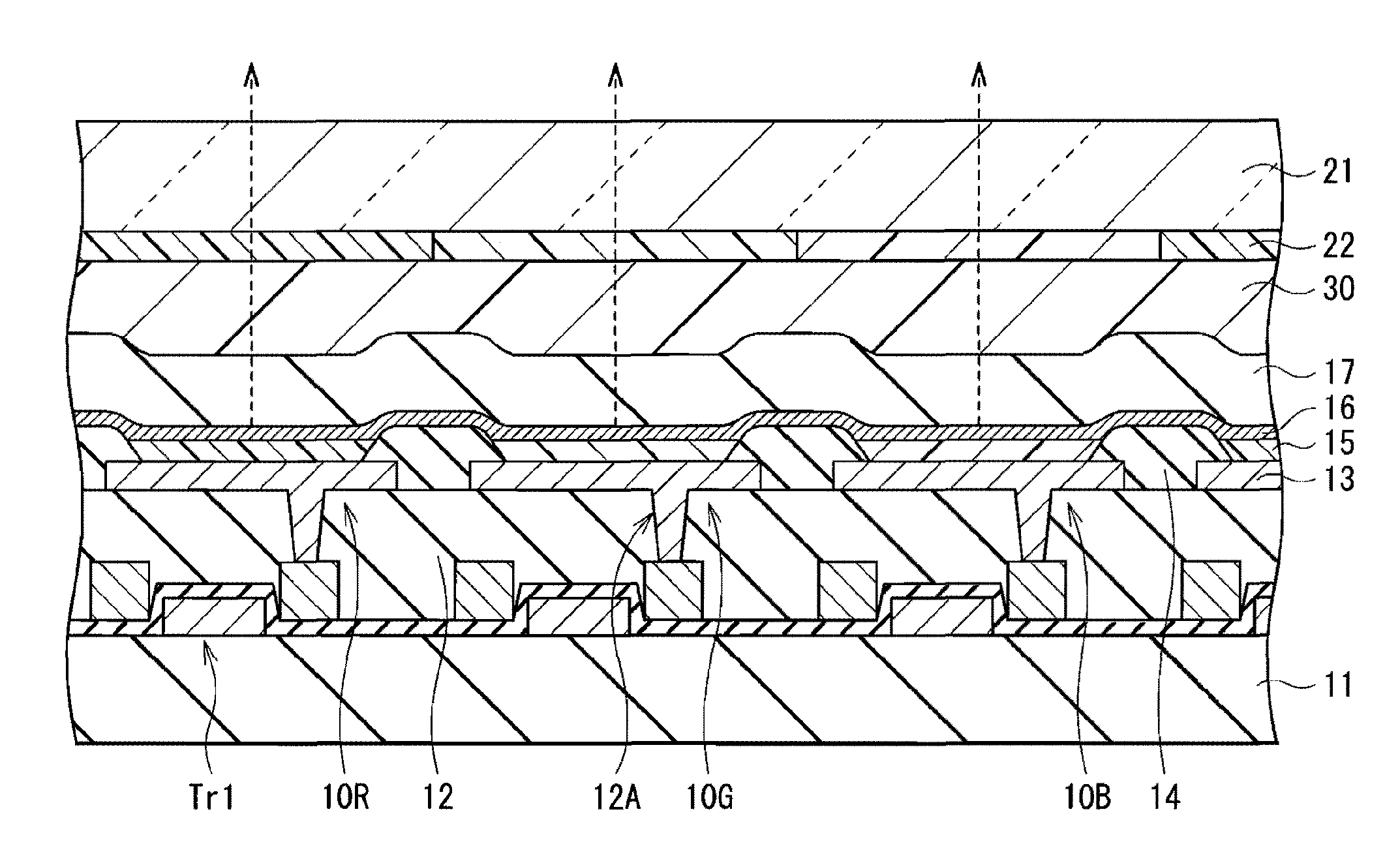
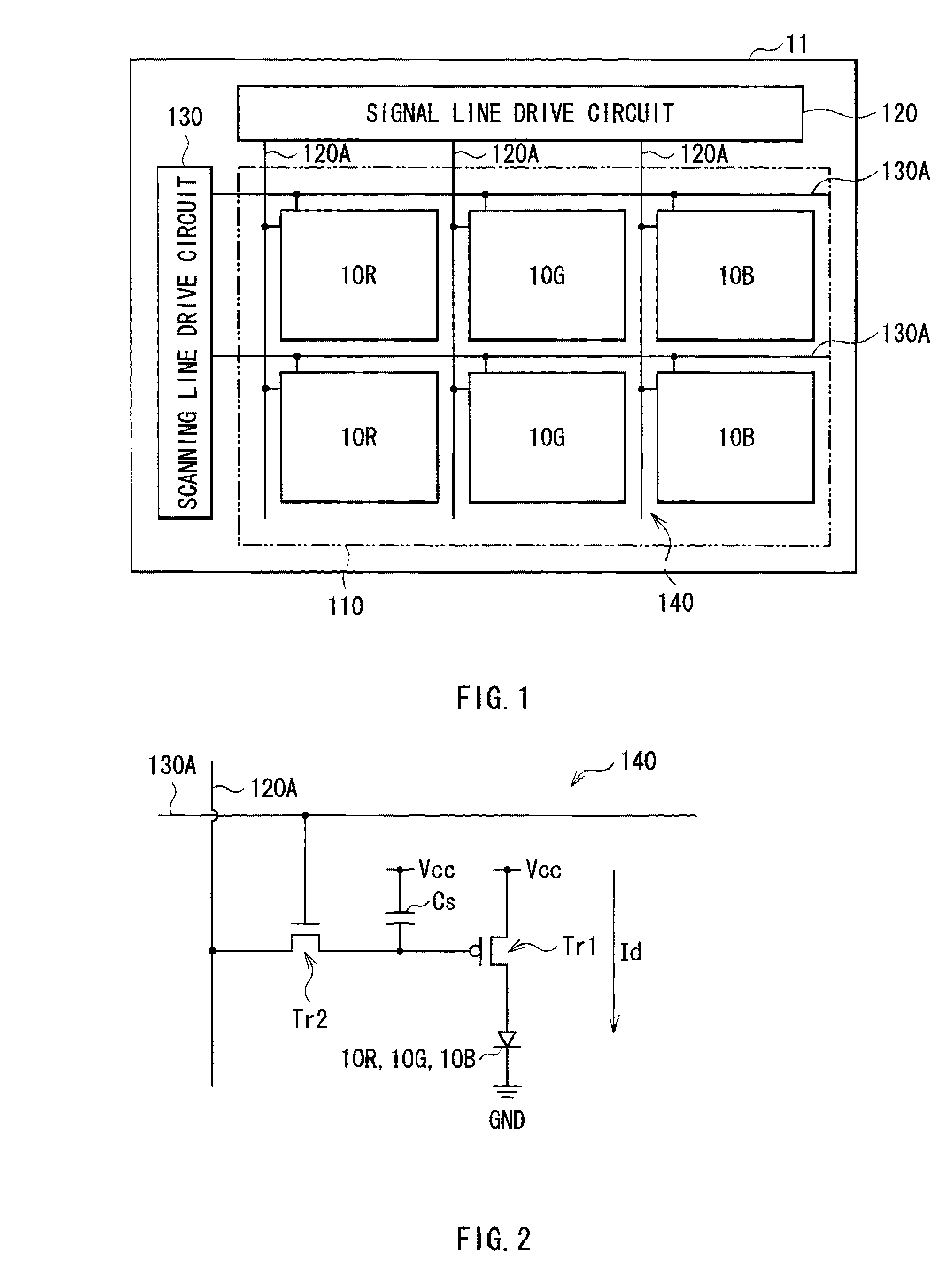
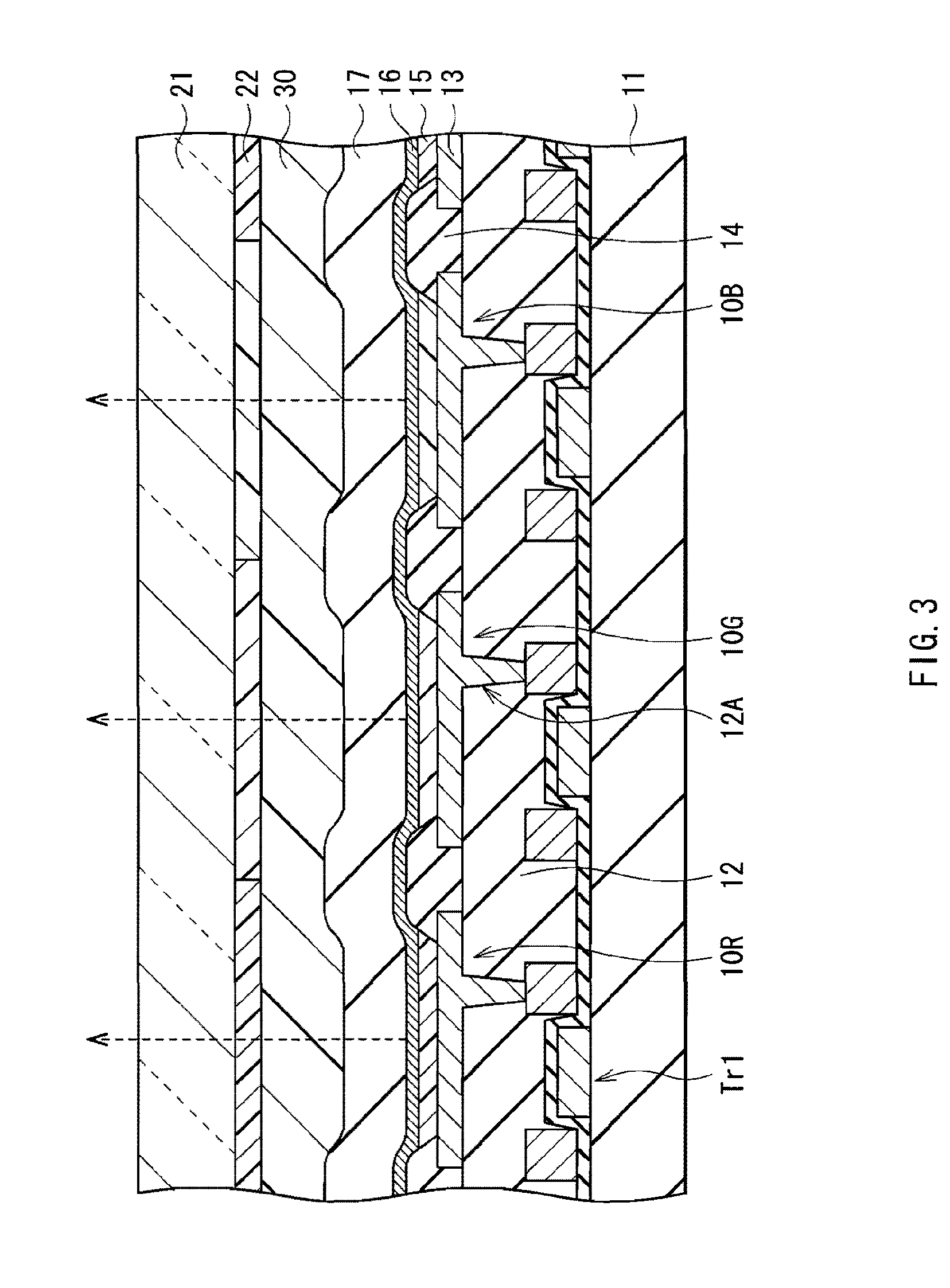
[0048]FIG. 1 shows a configuration of a display apparatus as a first embodiment of the present invention. The display apparatus is used as an ultrathin organic light emitting color display apparatus or the like. For example, a display area 110 in which a plurality of organic light emitting elements 10R, 10G, and 10B which will be described later are disposed in a matrix on a substrate 11 made of glass. Around the display area 110, a signal line drive circuit 120 and a scanning line drive circuit 130 as drivers for displaying a video image are formed.

[0049]A pixel drive circuit 140 is formed in the display area 110. FIG. 2 shows an example of the pixel drive circuit 140. The pixel drive circuit 140 is an active-type drive circuit formed in a layer under a first electrode 15 which will be described later, and having a drive transistor Tr1 and a write transistor Tr2, a capacitor (holding capacitor) Cs between the transistors Tr1 and Tr2, and the organic light emitting element 10R (10G,...

second embodiment

[0093]FIG. 13 is a diagram for explaining a method of manufacturing a display apparatus according to a second embodiment of the invention. In the second embodiment, in place of the irradiation power of the laser beam LB, relative speeds of the laser beam LB and the substrate 11, that is, the speed of the movable stage 51 (stage speed) is modulated. Except for this point, the manufacturing method of the second embodiment is the same as that of the first embodiment. The same operations and effects are obtained. Therefore, the same reference numerals are designated to corresponding elements, and description will be given.

[0094]FIG. 13 shows the relation between stage speed and contrast at certain irradiation powers in the forward path a1 and the backward path a2. FIG. 13 shows the case where the irradiation optical system 53 tilts with respect to the substrate 11 only by the angle φ, or the case where the section profile of the laser beam LB with respect to the plane perpendicular to t...

third embodiment

[0096]FIG. 14 shows a whole configuration of an annealing apparatus used in a third embodiment of the invention. In the third embodiment, by using the annealing apparatus 50 having three sets of the light source 52 and the irradiation optical system 53 (light sources 52A to 52C and irradiation optical systems 53A to 53C) as shown in FIG. 14, the throughput is further increased. However, in the case of moving the laser beam LB and the substrate 11 relative to each other by the movable stage 51, the stage speed may not be modulated independently in each of the irradiation optical systems 53. Consequently, in the third embodiment, the irradiation power of the laser beam LB is modulated in a manner similar to the first embodiment in each of the irradiation optical systems 53. Except for this point, the manufacturing method of the third embodiment is the same as that of the first embodiment, and the operations and effects are also the same. Therefore, the same reference numerals are desi...


PUM

PropertyMeasurementUnit
thicknessaaaaaaaaaa
thicknessaaaaaaaaaa
thicknessaaaaaaaaaa

Abstract

A method of manufacturing a semiconductor device includes the steps of: modifying a semiconductor film by applying a laser beam; and forming a semiconductor device on the modified semiconductor film. In the step of modifying the semiconductor film, the laser beam and the substrate are moved relative to each other in a first direction and a second direction which is opposite to the first direction, a change in an optical characteristic between an area irradiated with the laser beam and an area which is not irradiated with the laser beam in the substrate or an optical characteristic of the irradiated area is measured in each of the first and second directions, and irradiation power of the laser beam is modulated so that the difference between a measurement result in the first direction and a measurement result in the second direction lies in a predetermined range.

Description

CROSS REFERENCE TO RELATED APPLICATIONS[0001]The present invention contains subject matter related to Japanese Patent Application JP 2007-268347 filed in the Japanese Patent Office on Oct. 15, 2007, the entire contents of which being incorporated herein by reference.BACKGROUND OF THE INVENTION[0002]1. Field of the Invention[0003]The present invention relates to a method of manufacturing a semiconductor device suitable for manufacture of a TFT (Thin Film Transistor) used in, for example, a liquid crystal display or an organic light emitting display, a method of manufacturing a display apparatus, an apparatus of manufacturing a semiconductor device, and a display apparatus.[0004]2. Description of the Related Art[0005]A TFT substrate is used in an active matrix liquid crystal display or an organic light emitting display. The TFT substrate is obtained by forming a semiconductor film which is amorphous or of polycrystal having a relatively small grain diameter on a substrate, performing ...

Claims


Application Information

Patent Timeline
Patent Type & Authority Applications(United States)
IPC IPC(8): H01L33/00H01L21/00A61N5/00H01L21/20H01L21/265H01L21/268H01L21/336H01L29/786
CPCB23K26/0015B23K26/0042B23K26/032H01L27/1285H01L27/3244H01L51/0005H01L2251/5315H01L21/02691B23K26/0006B23K2103/54B23K2103/172B23K2103/56H10K59/12H10K71/135H10K2102/3026
Inventor MATSUNOBU, GOHTATSUKI, KOICHIINAGAKI, YOSHIOUMEZU, NOBUHIKOTSUKIHARA, KOICHI
Owner SONY CORP
Why Eureka
Try Eureka