Motor drive device and cooling device using the same

a technology of motor drive and cooling device, which is applied in the direction of pulse technique, dynamo-electric converter control, instruments, etc., can solve the problems of large heat generated, modulated duty ratio of pulse width, and heat from an lsi leading to thermorunaway, etc., to achieve the effect of improving linearity

Inactive Publication Date: 2009-04-16
ROHM CO LTD
View PDF1 Cites 27 Cited by
  • Summary
  • Abstract
  • Description
  • Claims
  • Application Information

AI Technical Summary

Benefits of technology

[0012]The present invention was made in view of these issues, and one gener...

Problems solved by technology

In such LSIs, as the operating speeds, that is, clock frequencies, become higher, amounts of heat generated become large.
There is a problem in that the generated heat from an LSI leads to thermorunaway in the LSI itself, or has an impact on neighboring circuits.
Furthermore, Patent Document 3 discloses technology...

Method used


Image

  • Motor drive device and cooling device using the same
  • Motor drive device and cooling device using the same
  • Motor drive device and cooling device using the same

Examples


first embodiment

[0036]An embodiment of the present invention relates to a motor drive apparatus used in a cooling device for cooling an electronic computer such as a desktop or notebook type of personal computer or workstation, or an electronic device such as a refrigerator, or the like.

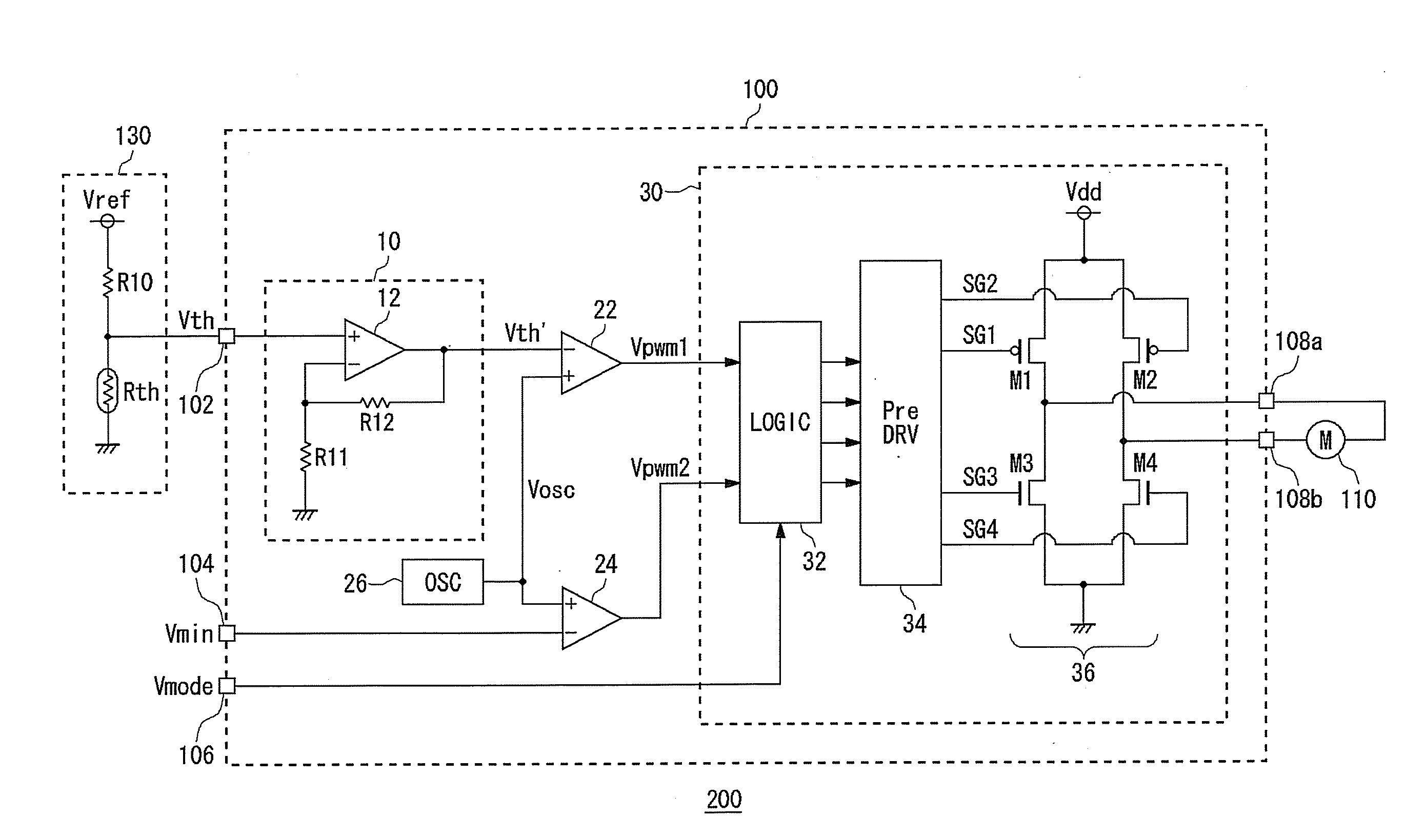
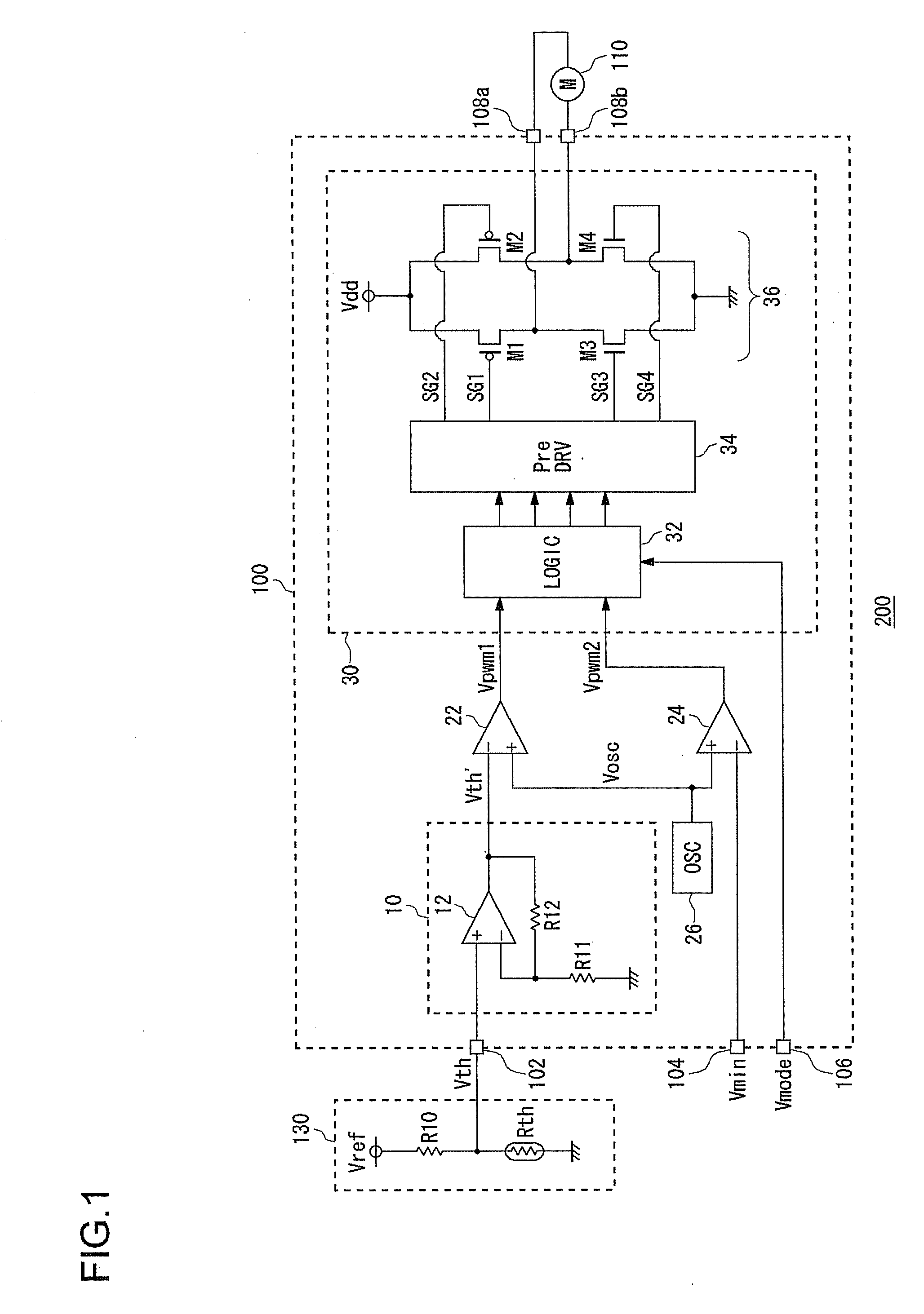
[0037]FIG. 1 is a circuit diagram showing a configuration of a cooling device 200 according to a first embodiment of the invention. The cooling device 200 includes a motor drive apparatus 100 and a fan motor 110.

[0038]The fan motor 110 is a single-phase full-wave motor, and is disposed opposite an object that is to be cooled, which is not shown in the figure. In the fan motor 110, a coil current, that is, an energization state (conduction state), is controlled by a drive signal outputted from the motor drive apparatus 100, and rotation is controlled.

[0039]The motor drive apparatus 100 is a function IC integrated as a unit on one semiconductor substrate. As terminals for input and output of signals, the motor drive a...

second embodiment

[0068]In the first embodiment, a setting was made for cases in which the predetermined minimum frequency setting voltage Vmin is inputted to the minimum frequency setting terminal 104. In contrast to this, in a second embodiment, an explanation is given concerning technology for controlling the frequency of the fan motor 110 by actively changing voltage inputted to the minimum frequency setting terminal 104.

[0069]FIG. 6 is a circuit diagram showing a configuration of a cooling device 200 according to the second embodiment. The cooling device 200 according to the present embodiment is further provided with a smoothing circuit 140 in addition to the cooling device 200 of FIG. 1. A pulse width modulated control signal Vcnt which controls the frequency of a fan motor 110 that is to be driven, is inputted to this cooling device 200, and the fan motor 110 is controlled based on this control signal Vcnt. In the present embodiment, a configuration of a motor drive apparatus 100 is similar t...


PUM


Abstract

A drive circuit of a fan motor is provided. In an embodiment of the drive circuit, a first PWM comparator compares a temperature detection voltage with a cyclic voltage, and outputs a first PWM signal. A second PWM comparator compares a minimum frequency setting voltage indicating a minimum frequency of the fan motor, with the cyclic voltage, and outputs a second PWM signal. The drive circuit combines the first PWM signal and the second PWM signal by a logical operation, to drive the fan motor. The drive circuit includes a first logic gate which generates a logical sum of the first PWM signal and the second PWM signal, and a second logic gate which generates a logical product of the first PWM signal and an inverted signal of the second PWM signal. The drive circuit switches drive mode based on the first logic gate and the second logic gate.

Description

BACKGROUND OF THE INVENTION[0001]1. Field of the Invention[0002]The present invention relates to motor drive technology.[0003]2. Description of the Related Art[0004]In recent years, with the speeding up of personal computers and workstations, operating speeds of LSIs (Large Scale Integrated circuits) for processing in CPUs (Central Processor Units), DSPs (Digital Signal Processors), and the like, have been increasing.[0005]In such LSIs, as the operating speeds, that is, clock frequencies, become higher, amounts of heat generated become large. There is a problem in that the generated heat from an LSI leads to thermorunaway in the LSI itself, or has an impact on neighboring circuits. Therefore, appropriate heat cooling of the LSIs has become a very important technology.[0006]As an example of technology for cooling the LSI, there is a cooling method comprising an air-cooling system by a cooling fan. In this method, for example, the cooling fan is installed facing a surface of the LSI, ...

Claims


Application Information

Patent Timeline
IPC IPC(8): G05D23/00H02P29/60H02P29/00H02P29/68
CPCH02P6/008H03K2017/0806H02P6/16H02P6/26H02P29/60G06F1/206H02P2209/09Y10S388/912
Inventor MIYAJIMA, SATOSHIHAYASHI, HIROAKIMISHIMA, TOMOFUMI
Owner ROHM CO LTD
Why Eureka
Try Eureka