Liquid Filter

Inactive Publication Date: 2009-04-23
A KAYSER AUTOMOTIVE SYST
View PDF11 Cites 1 Cited by
  • Summary
  • Abstract
  • Description
  • Claims
  • Application Information

AI Technical Summary

Benefits of technology

[0008]It is the object of the invention to design a liquid filter of the initially indicated generic type with the proviso that the production costs are lowered in relation to this prior art. This object is achieved in such a liquid filter through the features of the characterizing part of Claim 1.
[0011]Corresponding to the features of Claims 3 to 6, the cover is additionally equipped with means for fastening parts of a return line of a liquid supply system, for example of a fuel supply system, wherein a through-going pipe element serving this purpose is in turn made of aluminium for example and is held thereon by means of an adhesive bond. However, other materials for the through-going pipe element are not excluded. For this purpose, the cover can be provided with a half-shell-like recess which is open towards the upper side, with the result that subsequent insertion of the through-going pipe element is made possible.
[0013]Corresponding to the features of Claim 9, the through-going pipe element and / or the pipe elements are additionally arranged so as to be secured axially, at least in one direction, with positive locking in the recess or the connecting bores. This makes it possible to ensure an increased level of mounting reliability. At the same time, a positive-locking connection also makes it possible to constitute an axial limitation of insertion of a pipe element in a connecting bore.
[0017]Corresponding to the features of Claim 14, the pipe elements and / or the through-going pipe element can be formed from the same material as the lid. This opens up the possibility of optimally tailoring the adhesive to the materials used.

Problems solved by technology

The production of the cover by extrusion is characterized by a comparatively expensive die and finishing processes and cannot be regarded as ideal for this very reason.
The use of soldering or welding techniques to attach the pipe elements can also be considered as expensive, specifically not least because of the associated outlay on energy, apparatus and manual labour.
Against the economic background where liquid filters, in particular fuel filters, can be regarded as mass-produced products and have to be made available in large quantities, the design forms produced using the above-described techniques appear inappropriate with regard to the resultant cost requirement.

Method used


Image

  • Liquid Filter
  • Liquid Filter
  • Liquid Filter

Examples


Embodiment Construction

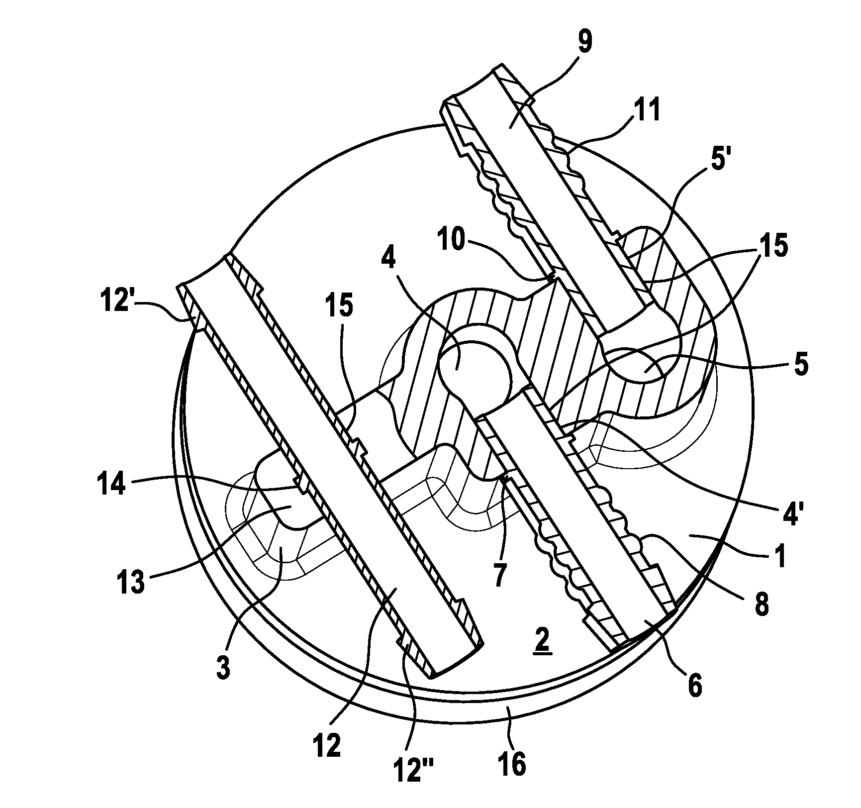
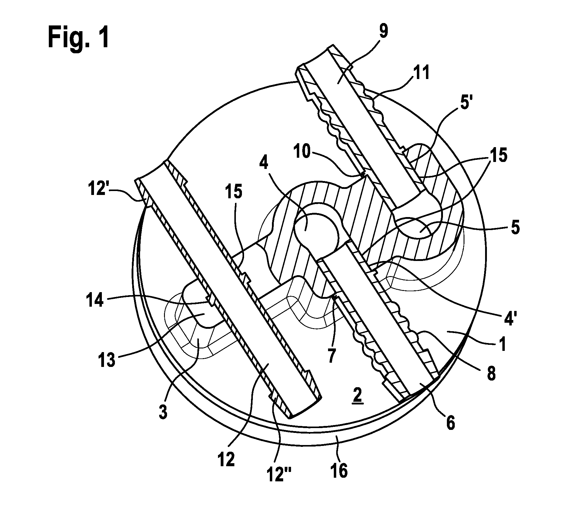
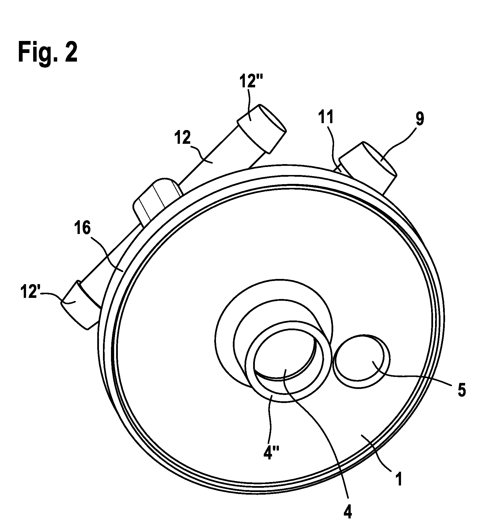
[0021]FIGS. 1 and 2 show a circular cover 1 in a partial sectional representation in a plane parallel to the end side of the housing, this cover being intended for the housing (not illustrated in the drawing) of a diesel fuel filter.

[0022]Extending on the upper side from the base plane 2 of the cover 1 that is oriented perpendicularly to the axis of the globally cylindrical housing is a superstructure 3 which has, in a central region, an outlet bore 4 running coaxially with respect to the axis of the housing and, in an edge region, an inlet bore 5 running parallel to the outlet bore. The two bores 4, 5 are continued in elbows within the superstructure 3 and terminate in respective connecting bores 4′, 5′ extending parallel to one another and to the base plane 2. On the underside with respect to the cover 1, the outlet bore 4 is continued in a pipe stop 4″.

[0023]Reference number 6 is used to designate a pipe element produced from aluminium which is plugged into the connecting bore 4′...


PUM

PropertyMeasurementUnit
Bondaaaaaaaaaa

Abstract

A liquid filter intended for use as a fuel filter is composed of a housing produced from aluminium by an extrusion process and of a cover (1) formed as an aluminium casting. The cover (1) is provided with connecting bores (4′, 5′) in which pipe elements (6, 9) which are intended for delivering and discharging fuel are held by means of an adhesive bond. This results in a cover which can be produced more cost-effectively than the prior art and which can further be used as a casting which can be employed in modular fashion, this casting allowing different variations for the connections of the pipe elements.

Description

BACKGROUND OF THE INVENTION[0001]This application claims priority to German patent application DE 20 2007 013 281.6 filed 21 Sep. 2007 and which is hereby incorporated by reference herein. The invention relates to a liquid filter corresponding to the features of the preamble of Claim 1.[0002]Examples of such liquid filters are fuel filters for diesel engines. These are routinely operated as full-flow filters and are composed of a cylindrical housing, for example made of metal, in which there is received a filter medium through which fuel to be treated flows and which exerts a retaining function on entrained solid particles, which can be considered as impurities, and of a cover releasably connected to one end side of this housing. The housing can additionally be configured with a view to trapping entrained water. The cover is provided in each case with bores which are intended for the connection of pipe elements serving respectively for delivering and discharging fuel.[0003]Fuel filt...

Claims


Application Information

Patent Timeline
IPC IPC(8): B01D35/30F02M37/32
CPCB01D35/30F02M37/22B01D2201/40B01D2201/302F02M37/32
Inventor FAY, RONALD
Owner A KAYSER AUTOMOTIVE SYST
Why Eureka
Try Eureka