Method for reclaim of carbon dioxide and nitrogen from boiler flue gas

Inactive Publication Date: 2009-04-23
CNPC GREAT WALL DRILLING COMPANY GWDC +1
View PDF3 Cites 33 Cited by
  • Summary
  • Abstract
  • Description
  • Claims
  • Application Information

AI Technical Summary

Benefits of technology

[0029]The said polyxinolum, an organic solvent with stable chemical properties and outstanding thermal stability, has low volatilization loss and is difficult to be degraded in use. Having low corrosivity, it demonstrates, to carbon dioxide, strong selective adsorption capability under pressurized conditions and excellent desorption capability under depressurized conditions.
[0030]In the present invention, optionally the carbon dioxide adsorption liquid further comprises a sodium orthovanadate as a corrosi

Problems solved by technology

In addition, the exploitation of many oil fields has entered into the middle or later period: though a series of measures such as water or steam injection have been taken, the recovery efficiency of crude oil is still low, the exploitation cost is high, and a lot of original oil in-place is difficult to or even cannot be exploited economically.
Worse still, the recovery efficiency is even lower while the cost is even higher with regard to low permeable oil, thick oil as well as crude oi

Method used


Image

  • Method for reclaim of carbon dioxide and nitrogen from boiler flue gas
  • Method for reclaim of carbon dioxide and nitrogen from boiler flue gas

Examples


Example

Example 1

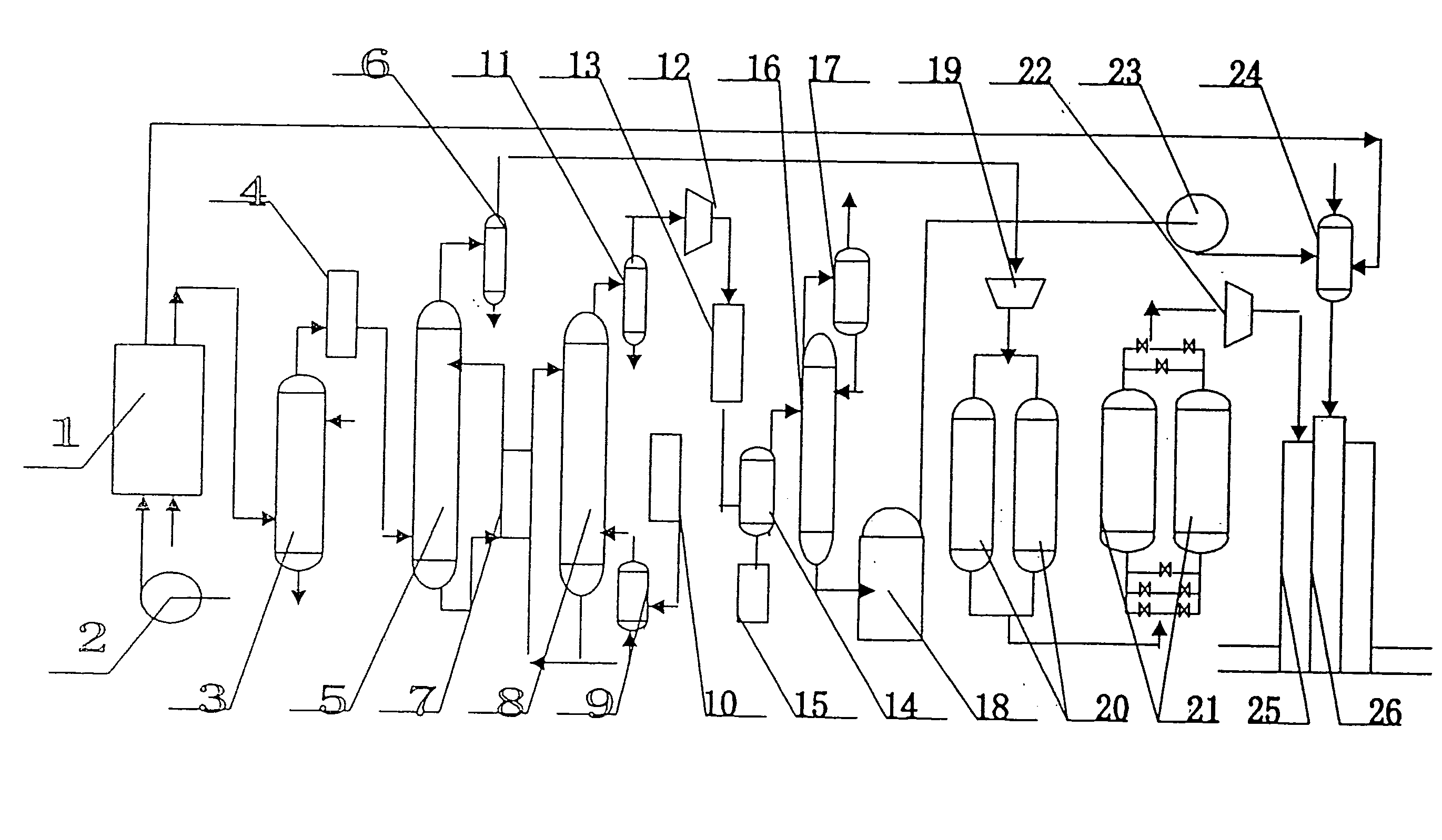
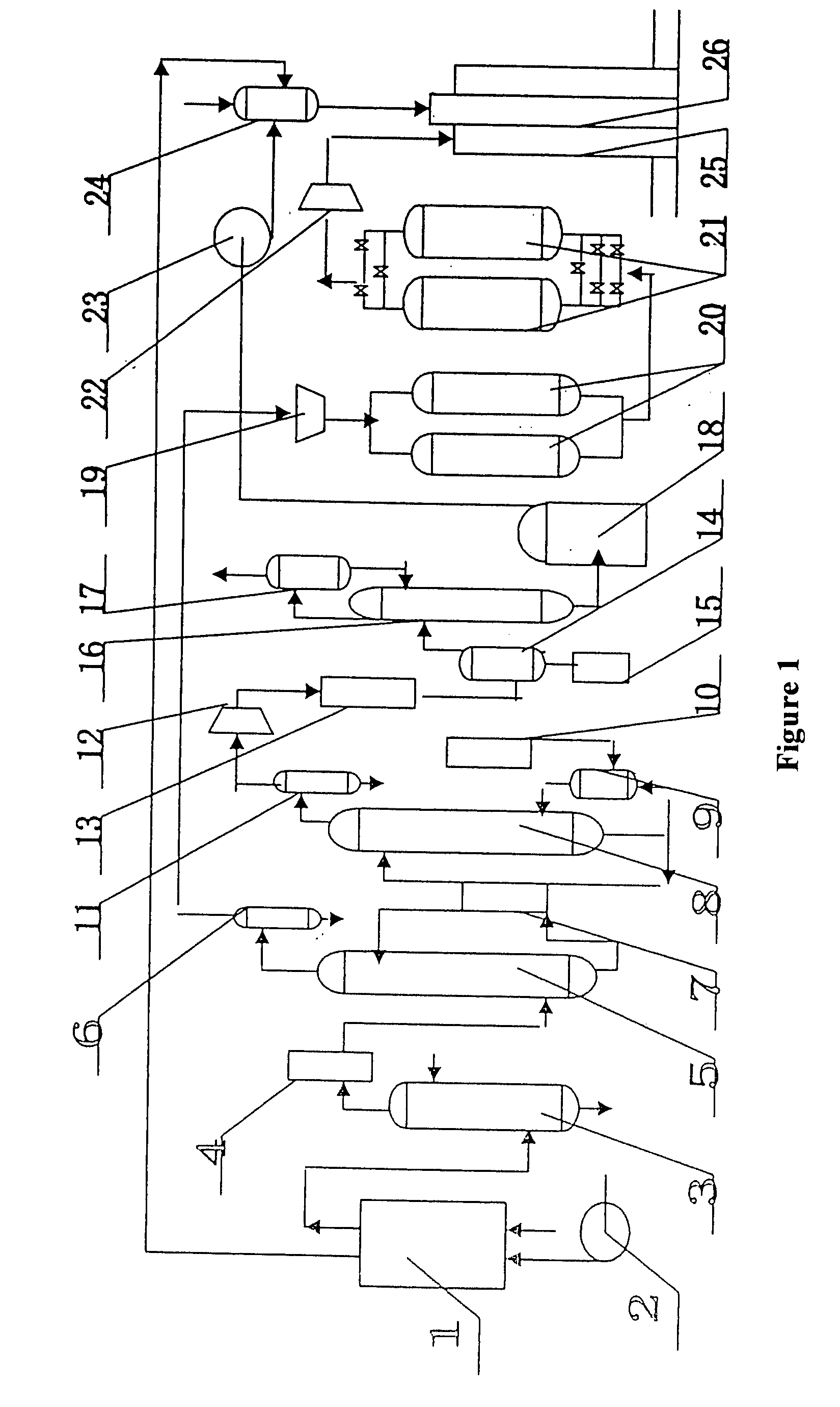
[0059]As is demonstrated by the FIGURE, the equipment provided by the invention for the reclaim of carbon dioxide from boiler flue gas as well as for the liquefaction of the reclaimed carbon dioxide for well injection oil recovery comprises a boiler 1, a high pressure water pump 2, a tower scrubber 3, an induced draft fan 4, an absorber 5, a separation tank 6, a heat exchanger 7, a regenerator 8, a reboiler 9, a steam boiler 10, a water segregator 11, a carbon dioxide compressor 12, a purifier 13, a liquefier 14, a congealer 15, a rectifying tower 16, a condenser 17, a storage tank 18, a nitrogen compressor 19, a drying beds 20, an adsorption beds 21, a nitrogen pressurizer 22, a carbon dioxide pump 23 and a mixing tank 24.

[0060]The structure, assembly and installment of the equipment provided by the invention for the reclaim of carbon dioxide from boiler flue gas as well as for the liquification of the reclaimed carbon dioxide for well injection oil recovery are as follows...

Example

Example 2

[0108]Take for example a coal boiler commonly used for oil recovery, which produces flue gas at 23 ton / hour. With the equipment stated in Example 1 and using the flue gas as raw material, carbon dioxide gas with purity of over 98%, the water content in which is less than 1.0%, may be reclaimed with the annual production capacity of 30,000 tons. Meanwhile, nitrogen gas with purity of over 93% may also be reclaimed with the production capacity of 36,000 ton / year. The reclaimed nitrogen contains oxygen (6.0% by volume), water (1.0% by volume), sulfur dioxide (<50 ppm) and nitrogen dioxides (<20 ppm).

[0109]Shown in the following Table 1 is the composition of the flue gas of the coal boiler in the method provided by the invention.

TABLE 1IngredientUnitData1actual flue gas emissionm3 / h46000.02actual flue gas temperature° C.123.683content of CO2 in the flue%9.52gas4content of SO2%0.00295content of N2%72.016content of O2%6.9587content of H2O%11.510

[0110]The present example employs t...


PUM

PropertyMeasurementUnit
Fractionaaaaaaaaaa
Fractionaaaaaaaaaa
Fractionaaaaaaaaaa

Abstract

This invention discloses a method for the reclaim of carbon dioxide and nitrogen from boiler flue gas, which includes: the flue gas enters into the water-washing and desulfurizing tower from the inferior part and contacts the sulfide solution flowing backward for the cleaning and desulfurizing of the flue gas; the desulfurized flue gas is introduced to the inferior part of the chemical absorber, where the contained carbon dioxide contacts the carbon dioxide adsorption liquid (containing, by the total weight of the liquid, of, besides water, 20-60% water solution of compound amine, 5-10% polyxinolum, 1-5% antioxygen and 1-5% corrosion inhibitor) flowing backward;
    • The adsorption liquid coming from the bottom of the absorber and having absorbed carbon dioxide, after heated when passing through heat exchangers, is sent to the top of the carbon dioxide regenerator and flows down through the packing layer; carbon dioxide is emitted out from the top of the regenerator;
    • Nitrogen separated out from the top of the chemical absorber is freeze dried to reduce the content of saturated water to lower than 1.0%.
This invention discloses a piece of equipment for the reclaim of carbon dioxide and nitrogen from boiler flue gas.

Description

RELATED APPLICATION[0001]This application claims the benefit of priority from Chinese Patent Application No. 200710163245.6, filed on Oct. 22, 2007, the entirety of which is incorporated herein by reference.FIELD OF THE INVENTION[0002]This invention relates to a method for the reclaim of carbon dioxide and nitrogen from boiler flue gas, especially from the flue gas of steam boilers used in oil fields. The reclaimed carbon dioxide and nitrogen can be employed to assist the exploitation of thick crude oil (or called “dense” crude oil).BACKGROUND OF THE INVENTION[0003]In oil fields, the reservoir bed belonging to the continental facies bears considerable heterogeneity during the process of sedimentation. Part of the crude oil containing water has fast rising velocity for its high viscosity. In addition, the exploitation of many oil fields has entered into the middle or later period: though a series of measures such as water or steam injection have been taken, the recovery efficiency of...

Claims


Application Information

Patent Timeline
IPC IPC(8): B01D53/14C01B32/50
CPCB01D53/1475B01D53/1493B01D53/60Y02C10/06B01D2257/302B01D2257/404B01D2257/504B01D53/75Y02C20/40
Inventor ZHANG, FENGSHANGAO, YUANWEN
Owner CNPC GREAT WALL DRILLING COMPANY GWDC
Why Eureka
Try Eureka