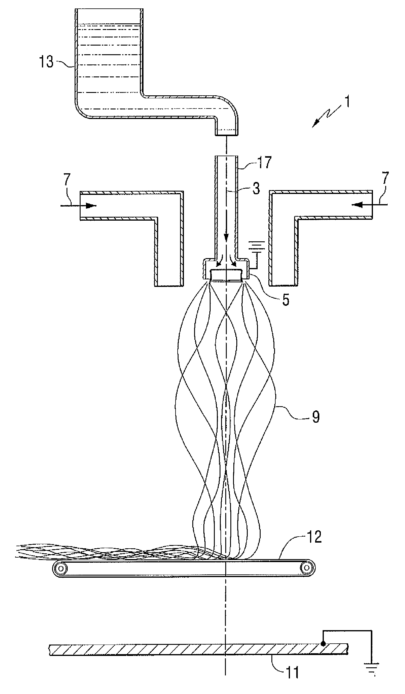
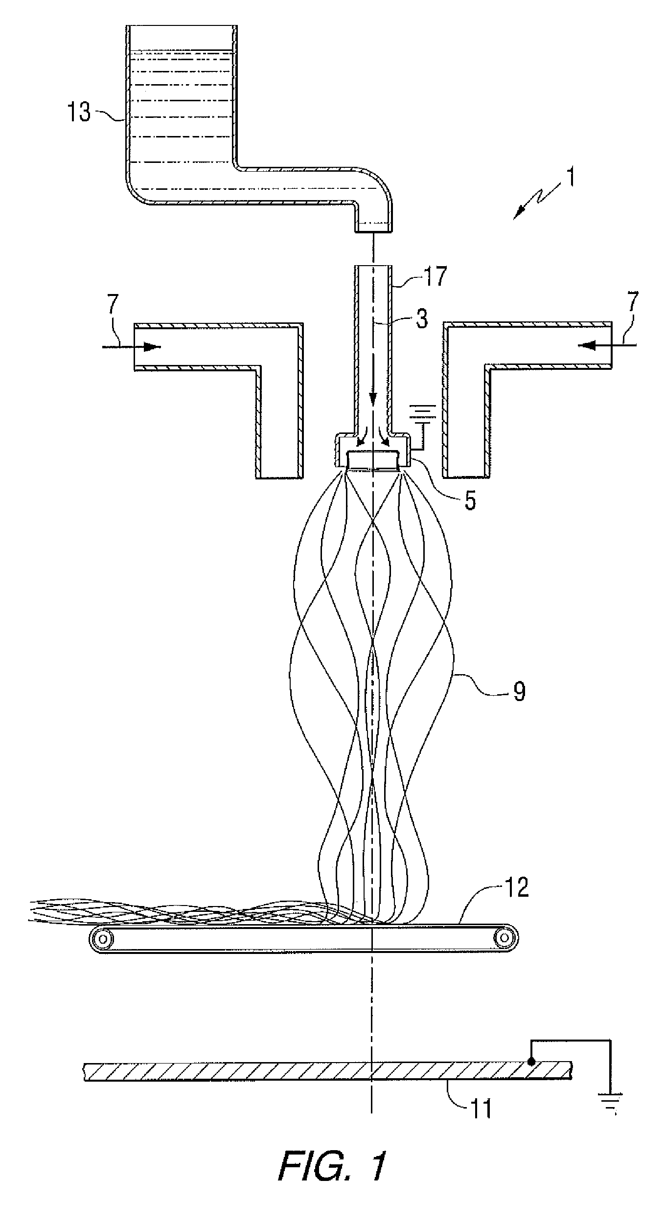
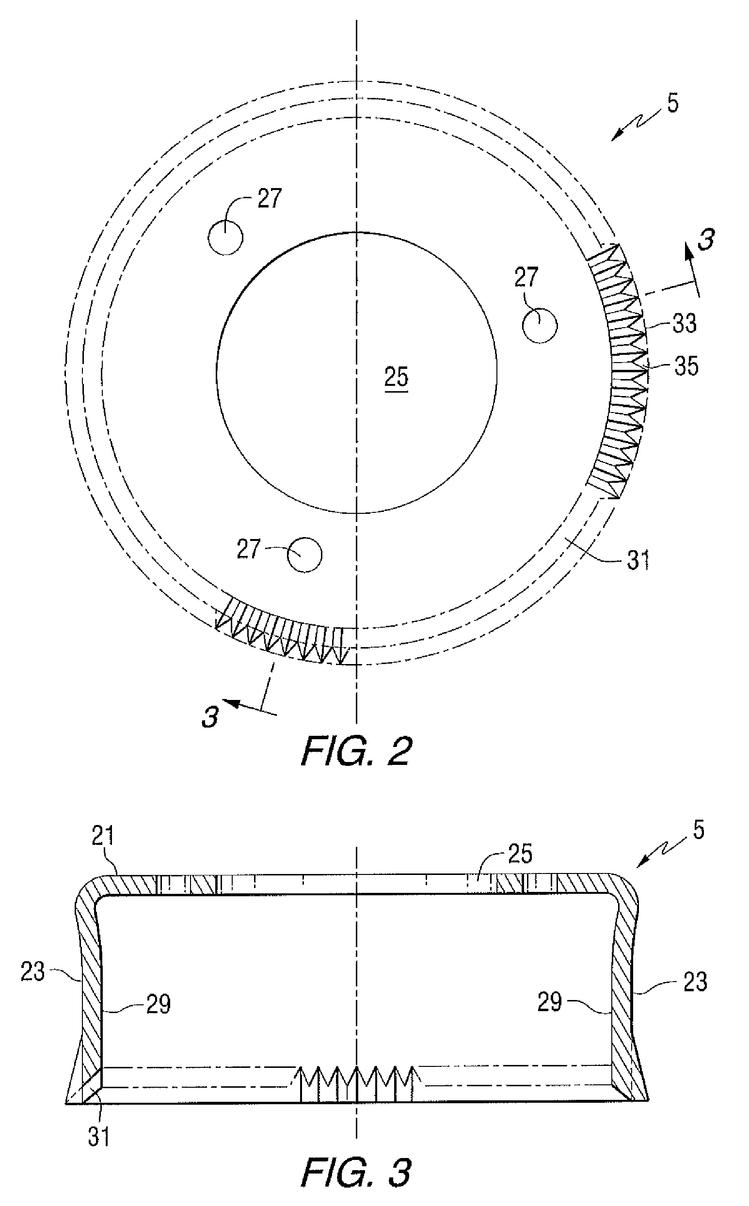
Fiber formation by electrical-mechanical spinning
a technology of electrical-mechanical spinning and fibers, applied in the field of fibers, can solve problems affecting the quality and quantity of fibers
- Summary
- Abstract
- Description
- Claims
- Application Information
AI Technical Summary
Benefits of technology
Problems solved by technology
Method used
Image

Examples
example a
[0033]An acrylic-silane polymer was prepared as follows.
[0034]With reference to Table 1 below, a reaction flask was equipped with a stirrer, thermocouple, nitrogen inlet and a condenser. Charge A was then added and stirred with heat to reflux temperature (75° C.-80° C.) under nitrogen atmosphere. To the refluxing ethanol, Charge B and Charge C were simultaneously added over three hours. The reaction mixture was held at reflux condition for two hours. Charge D was then added over a period of 30 minutes. The reaction mixture was held at reflux condition for two hours and subsequently cooled to 30° C.
TABLE 1Example ACharge A (weight in grams)Ethanol SDA 40B1477.5Charge B (weight in grams)Methyl Methacrylate0.2Acrylic acid11.5Silquest A-1742134.42-hydroxylethylmethacrylate45.8n-Butyl acrylate0.2Acrylamide7.2Ethanol SDA 40B206.5Charge C (weight in grams)Vazo 6738.1Ethanol SDA 40B101.7Charge D (weight in grams)Vazo 672.0Ethanol SDA 40B12.0% Solids21.3Acid value (solution)10.51Denatured et...
example b
[0037]An acrylic-silane polymer was prepared as follows.
[0038]With reference to Table 2 below, a reaction flask was equipped with a stirrer, thermocouple, nitrogen inlet and a condenser. Charge A was then added and stirred with heat to reflux temperature (75° C.-80° C.) under nitrogen atmosphere. To the refluxing ethanol, Charge B and Charge C were simultaneously added over three hours. The reaction mixture was held at reflux condition for two hours. Charge D was then added over a period of 30 minutes. The reaction mixture was held at reflux condition for two hours and subsequently cooled to 30° C.
TABLE 2Example ACharge A (weight in grams)Ethanol SDA 40B1288.0Charge B (weight in grams)Methyl Methacrylate16.0Acrylic acid6.9Silquest A-174281.12-hydroxylethylmethacrylate0.1n-Butyl acrylate0.1Glycidyl Methacrylate11.6Ethanol SDA 40B124.5Charge C (weight in grams)Vazo 67349.0Ethanol SDA 40B61.1Charge D (weight in grams)Vazo 671.2Ethanol SDA 40B7.2% Solids18.5Acid value (solution)8.91Dena...
example c
[0040]An inorganic sol gel polymer was prepared as follows.
[0041]Deionized water (36 grams) was placed in a jar, and polyvinyl alcohol (4 grams, Aldrich, Catalog 36311, CAS [9002-89-5], 96% hydrolyzed, and MW 85,000-100,000) was added to the water while stirring magnetically. This mixture was warmed to 80° C. in a hot water bath to affect dissolution. More deionized water (40 grams) was added to this warm aqueous polyvinyl alcohol solution while continuing to stir. To this warm, diluted aqueous polyvinyl alcohol solution was added colloidal silica dispersion (120 grams, MT-ST Silica, Nissan Chemical Industries, LTD., about 30% silica in methanol) while continuing to stir. Viscosity of this polyvinyl alcohol, silica solution was determined to be A− by the method of ASTM-D1545.
PUM
| Property | Measurement | Unit |
|---|---|---|
| Diameter | aaaaa | aaaaa |
| Diameter | aaaaa | aaaaa |
| Electric potential / voltage | aaaaa | aaaaa |
Abstract
Description
Claims
Application Information
 - Generate Ideas
- Intellectual Property
- Life Sciences
- Materials
- Tech Scout
- Unparalleled Data Quality
- Higher Quality Content
- 60% Fewer Hallucinations
Browse by: Latest US Patents, China's latest patents, Technical Efficacy Thesaurus, Application Domain, Technology Topic, Popular Technical Reports.
© 2025 PatSnap. All rights reserved.Legal|Privacy policy|Modern Slavery Act Transparency Statement|Sitemap|About US| Contact US: help@patsnap.com