

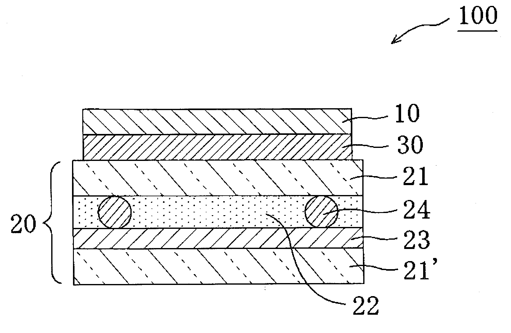
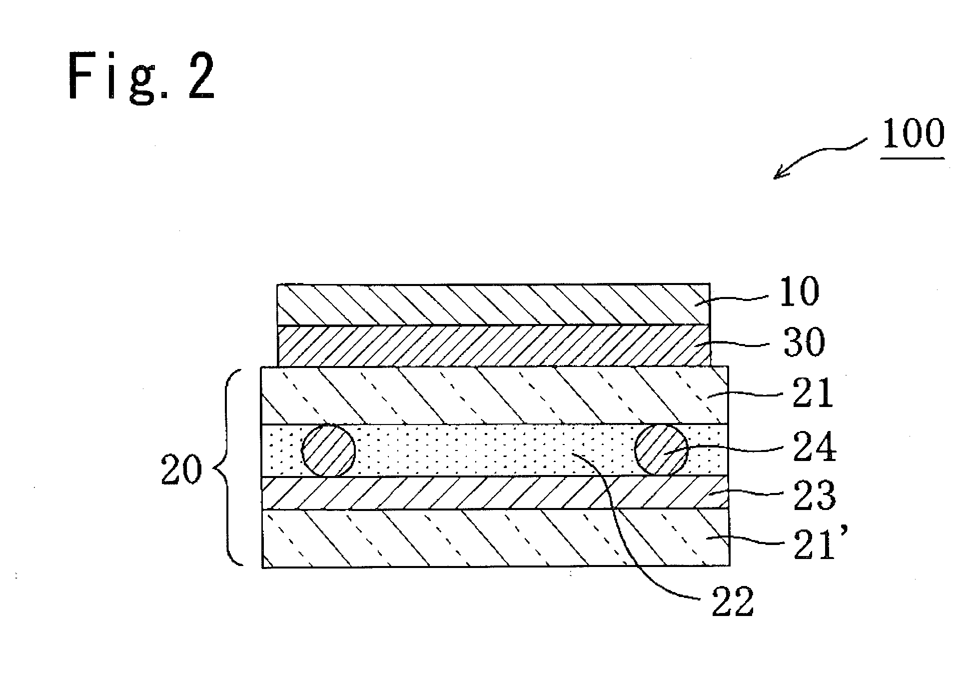
Polarizing plate with an optical compensation layer, liquid crystal panel, liquid crystal display apparatus, and image display apparatus using the polarizing plate with an optical compensation layer
a technology of optical compensation layer and polarizing plate, which is applied in the direction of polarising elements, optics, instruments, etc., can solve the problems of retardation film damage, retardation film degradation, and opaqueness, and achieve enhanced viewing angle properties, high contrast, and reduced thickness
- Summary
- Abstract
- Description
- Claims
- Application Information
AI Technical Summary
Benefits of technology
Problems solved by technology
Method used
Image

Examples
example 1
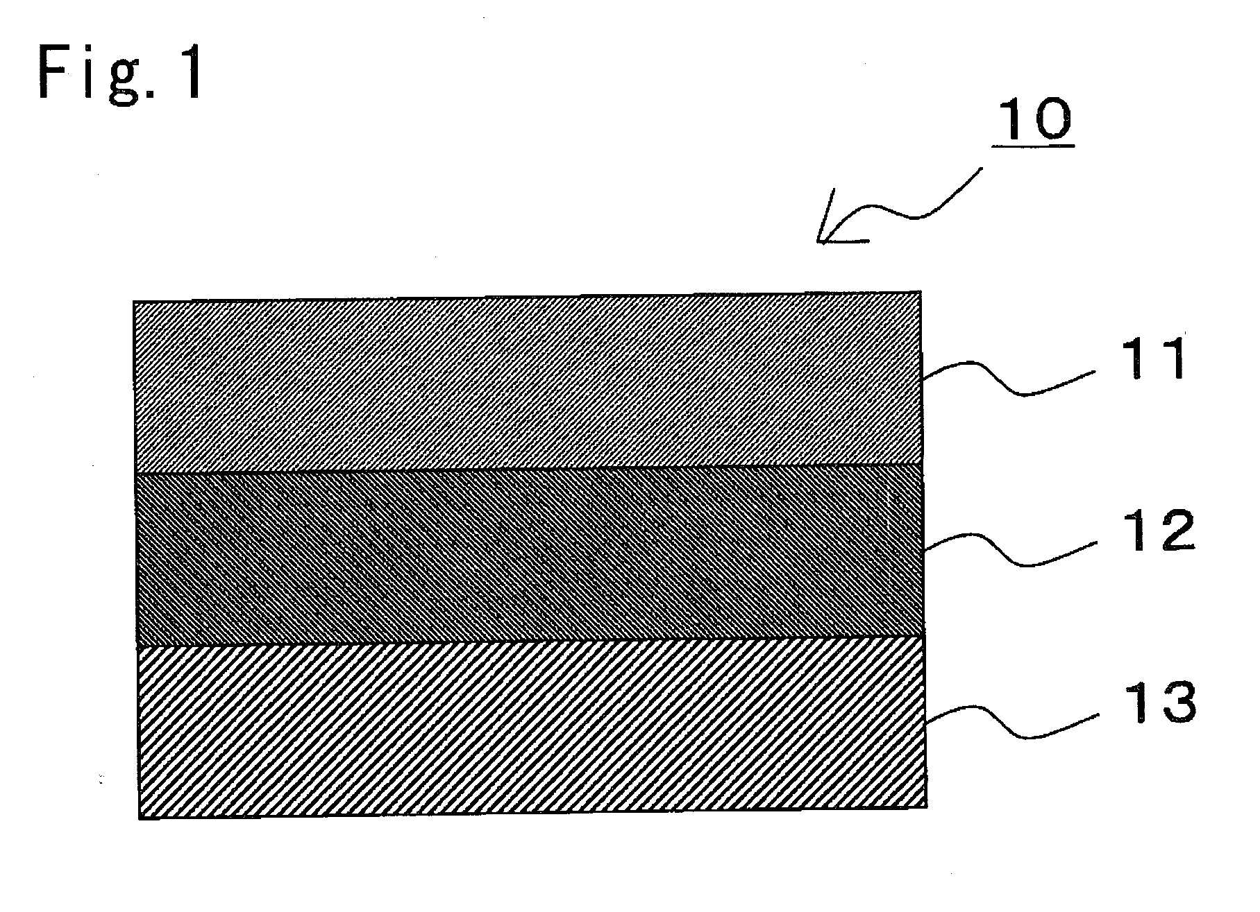
Production of a Polarizer
[0140]A commercially available polyvinyl alcohol (PVA) film (manufactured by Kurary Co., Ltd.) was dyed in an aqueous solution containing iodine, and uniaxially stretched about 6 times between rolls with different speeds in an aqueous solution containing boric acid, whereby along polarizer was obtained. Commercially available TAC films (manufactured by Fujiphoto Film Co., Ltd.) were attached to both surfaces of the polarizer with a PVA-based adhesive, whereby a polarizing plate (protective layer / polarizer / protective layer) with an entire thickness of 100 μm was obtained. The polarizing plate was punched to a size of 20 cm (length)×30 cm (width) so that the absorption axis of the polarizer was placed in a longitudinal direction.
[0141](Production of a First Optical Compensation Layer)
[0142]A stretched denatured polycarbonate film (PUREACE WR (trade name) manufactured by Teijin Ltd.) with a thickness of 77 μm was used as a film for a first optical compensation ...
example 2
[0147]In Example 2, a laminate of a cholesteric alignment fixed layer and a resin film having the following configuration was used as a second optical compensation layer to be a negative C-plate, instead of the norbornene-based resin film used in Example 1. Specifically, the second optical compensation layer of Example 2 was produced as follows.
[0148](Production of a Second Optical Compensation Layer)
[0149]A liquid crystal application liquid was produced by uniformly mixing 90 parts by weight of a nematic liquid crystalline compound represented by formula (10) mentioned below, 10 parts by weight of a chiral agent represented by formula (38) mentioned below, 5 parts by weight of a photopolymerization initiator (IRGACURE 907, manufactured by Ciba Specialty Chemicals, Co., Ltd.), and 300 parts by weight of methylethyl ketone. Next, the liquid crystal application liquid was applied onto a substrate (biaxially stretched PET film). Then the whole was subjected to heat treatment at 80° C. ...
PUM
 Abstract
Description
Claims
Application Information