[0007]In various exemplary embodiments, the present invention utilizes dynamically or non-dynamically programmable toolpaths to create short chips, regardless of the cutting conditions present.
Machine tool axes capabilities are utilized, not only to position the cutting tool in relation to the workpiece, but also to generate motion that results in short chips. This eliminates the problem of operator
exposure to dangerous, and potentially hazardous, materials during the manual chip removal process, reduces the temperature of the cutting tool, and enhances the ability to implement automated manufacturing cells.
[0008]In one exemplary embodiment, the present invention provides a computer
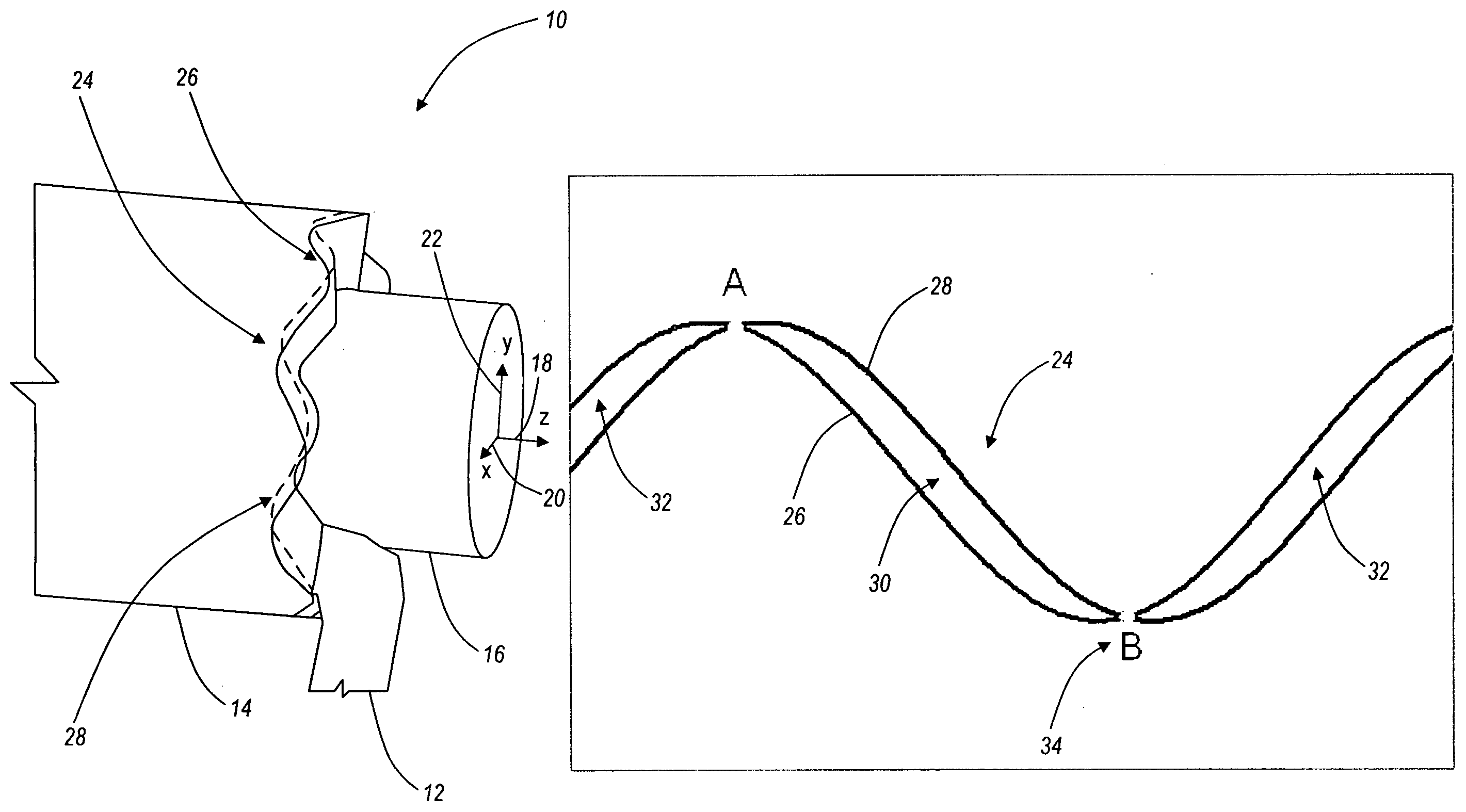
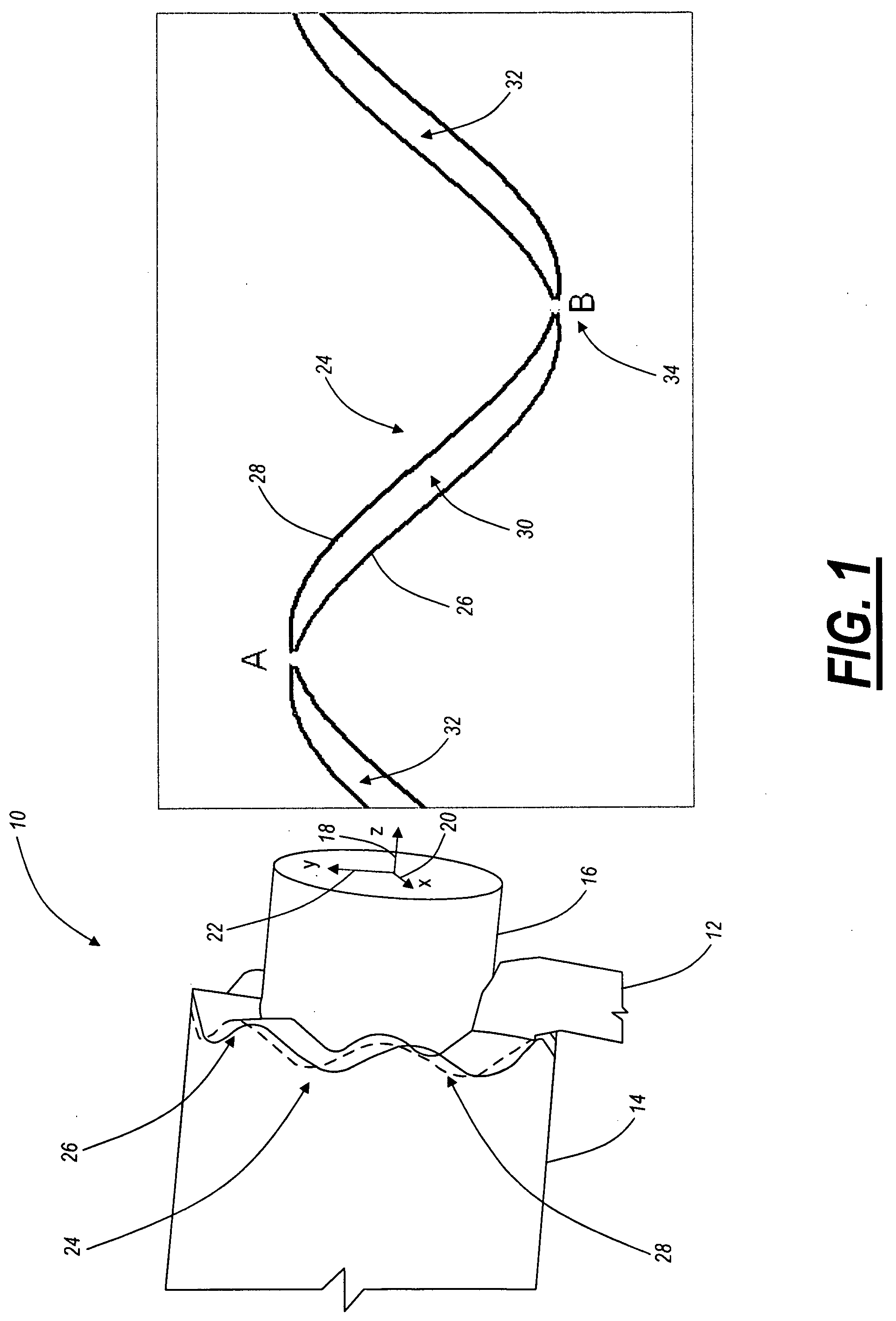
numerical control (CNC)-based method for chip breaking and the like in turning, boring, and other applications, including: engaging a workpiece with a cutting tool in a feed direction along a toolpath; and superimposing an oscillation in the feed direction on the toolpath such that one or more interrupted cuts and one or more chips are produced. The workpiece comprises an axis. The feed direction is one or more of parallel to, perpendicular to, and disposed at an angle to the axis of the workpiece. The oscillation superimposed in the feed direction on the toolpath includes a waveform selected from the group consisting of a
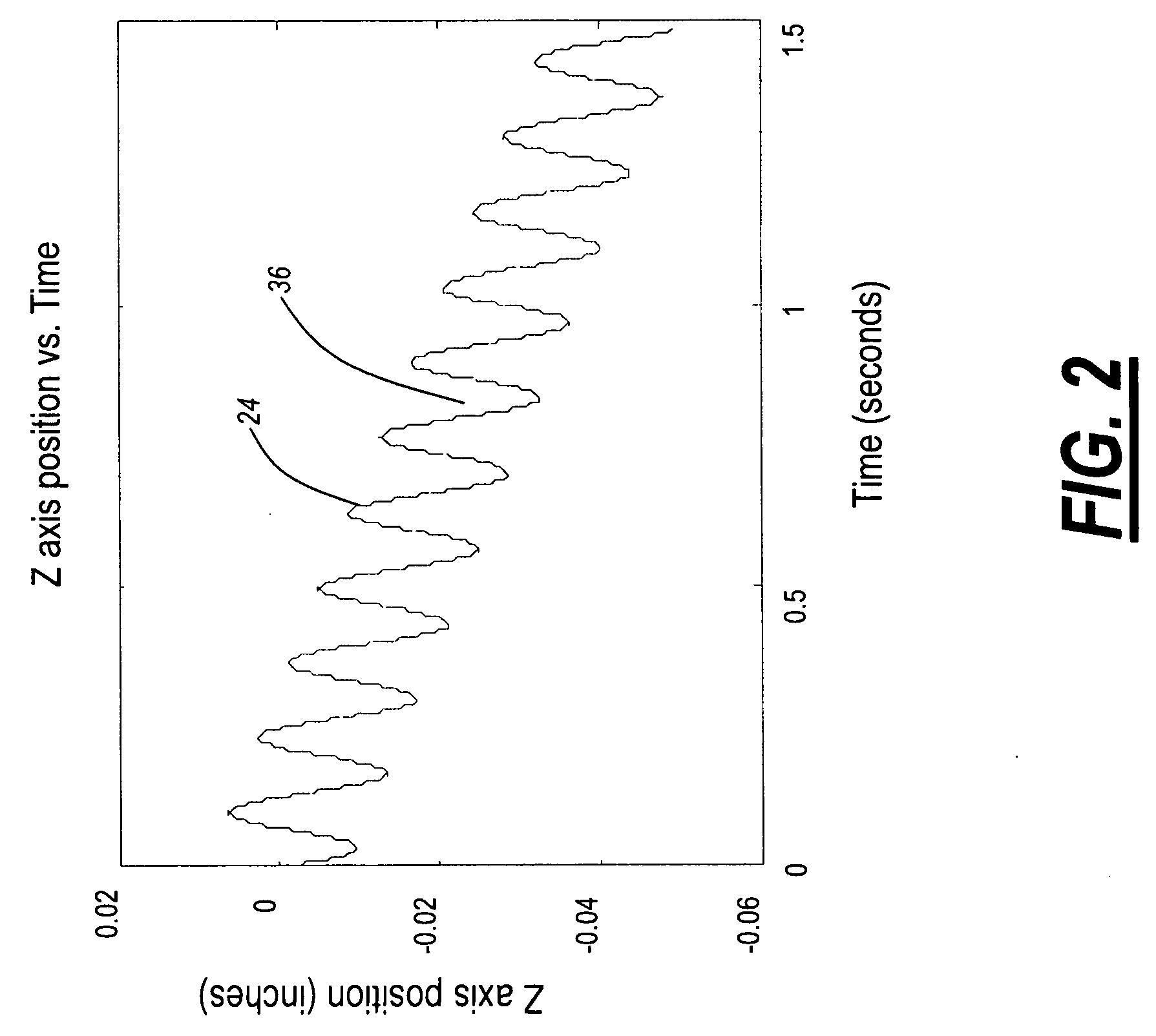
sinusoidal waveform, a regular waveform, an irregular waveform, and a random waveform. The method also includes varying a phase of the waveform with one or more of time and workpiece position. The method further includes dynamically or non-dynamically varying the oscillation superimposed in the feed direction on the toolpath. Dynamically or non-dynamically varying the oscillation superimposed in the feed direction on the toolpath includes dynamically or non-dynamically varying one or more of an amplitude, a frequency, and a phase of the oscillation superimposed in the feed direction on the toolpath. Dynamically or non-dynamically varying the oscillation superimposed in the feed direction on the toolpath also includes dynamically or non-dynamically varying the oscillation superimposed in the feed direction on the toolpath based on one or more of an inputted spindle speed, oscillation frequency,
oscillation amplitude, cutting tool feed rate, workpiece geometry, part geometry, chip length, probability of producing a predetermined chip length, controller characteristic, machine characteristic, thermal consideration, cutting tool characteristic, part surface texture,
residual stress factor, and fatigue life factor. The toolpath is selected responsive to a part surface resulting from a previous toolpath. Optionally, the method is utilized to one or more of control
cutting tool wear, manage cutting temperature, create a structured surface, and improve a
surface finish.
[0009]In another exemplary embodiment, the present invention provides a computer numerical control (CNC)-based
system for chip breaking and the like in turning, boring, and other applications, including: a cutting tool for engaging a workpiece in a feed direction along a toolpath; and a controller for superimposing an oscillation in the feed direction on the toolpath such that one or more interrupted cuts and one or more chips are produced. The workpiece comprises an axis. The feed direction is one or more of parallel to, perpendicular to, and disposed at an angle to the axis of the workpiece. The oscillation superimposed in the feed direction on the toolpath includes a waveform selected from the group consisting of a
sinusoidal waveform, a regular waveform, an irregular waveform, and a random waveform. The
system also includes an
algorithm for varying a phase of the waveform with one or more of time and workpiece position. The
system further includes an
algorithm for dynamically or non-dynamically varying the oscillation superimposed in the feed direction on the toolpath. Dynamically or non-dynamically varying the oscillation superimposed in the feed direction on the toolpath includes dynamically or non-dynamically varying one or more of an amplitude, a frequency, and a phase of the oscillation superimposed in the feed direction on the toolpath. Dynamically or non-dynamically varying the oscillation superimposed in the feed direction on the toolpath also includes dynamically or non-dynamically varying the oscillation superimposed in the feed direction on the toolpath based on one or more of an inputted spindle speed, oscillation frequency,
oscillation amplitude, cutting tool feed rate, workpiece geometry, part geometry, chip length, probability of producing a predetermined chip length, controller characteristic, machine characteristic, thermal consideration, cutting tool characteristic, part surface texture,
residual stress factor, and fatigue life factor. The toolpath is selected responsive to a part surface resulting from a previous toolpath. Optionally, the system is utilized to one or more of control
cutting tool wear, manage cutting temperature, create a structured surface, and improve a
surface finish.
[0010]In a further exemplary embodiment, the present invention provides a computer numerical control (CNC)-based method for chip breaking and the like in turning, boring, and other applications, including: engaging a workpiece with a cutting tool in a feed direction along a first toolpath segment; and engaging the workpiece with the cutting tool in the feed direction along a second toolpath segment; wherein an interaction of the first toolpath segment and the second toolpath segment results in one or more interrupted cuts and one or more chips being produced. Optionally, the method is utilized to one or more of control
cutting tool wear, manage cutting temperature, create a structured surface, and improve a surface finish.

