

Control unit for internal combustion engine
a control unit and internal combustion engine technology, applied in the direction of electrical control, process and machine control, instruments, etc., can solve the problems of increasing the heating of the driving circuit, unable to actuate the injector, and inability to enable electric current to flow to the injector solenoid coil b>10, so as to prevent the further deterioration of the damage of the boost circuit, prevent the build-up of heat, and prevent the effect of regenerative curren
- Summary
- Abstract
- Description
- Claims
- Application Information
AI Technical Summary
Benefits of technology
Problems solved by technology
Method used
Image

Examples
embodiment 1
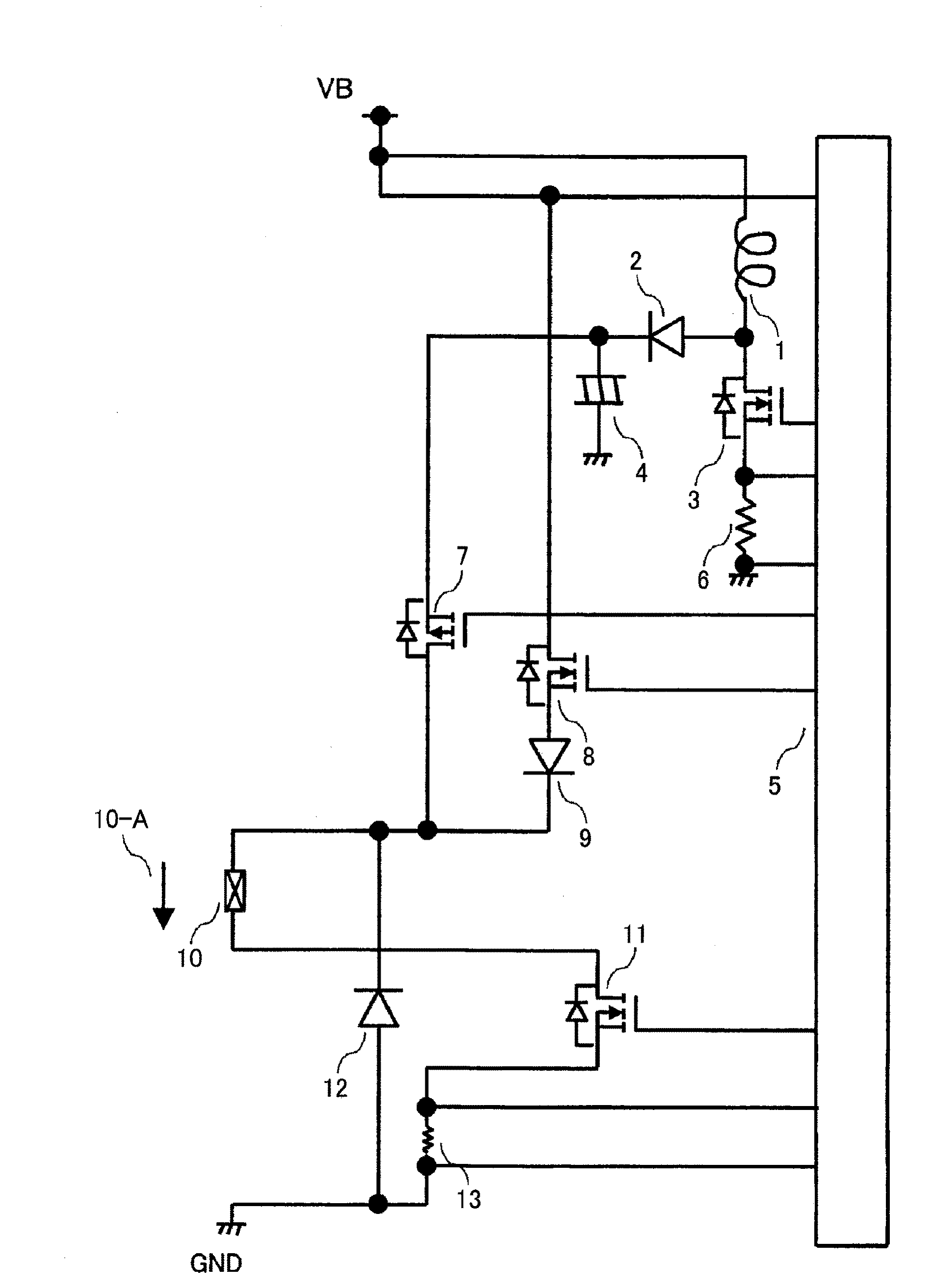
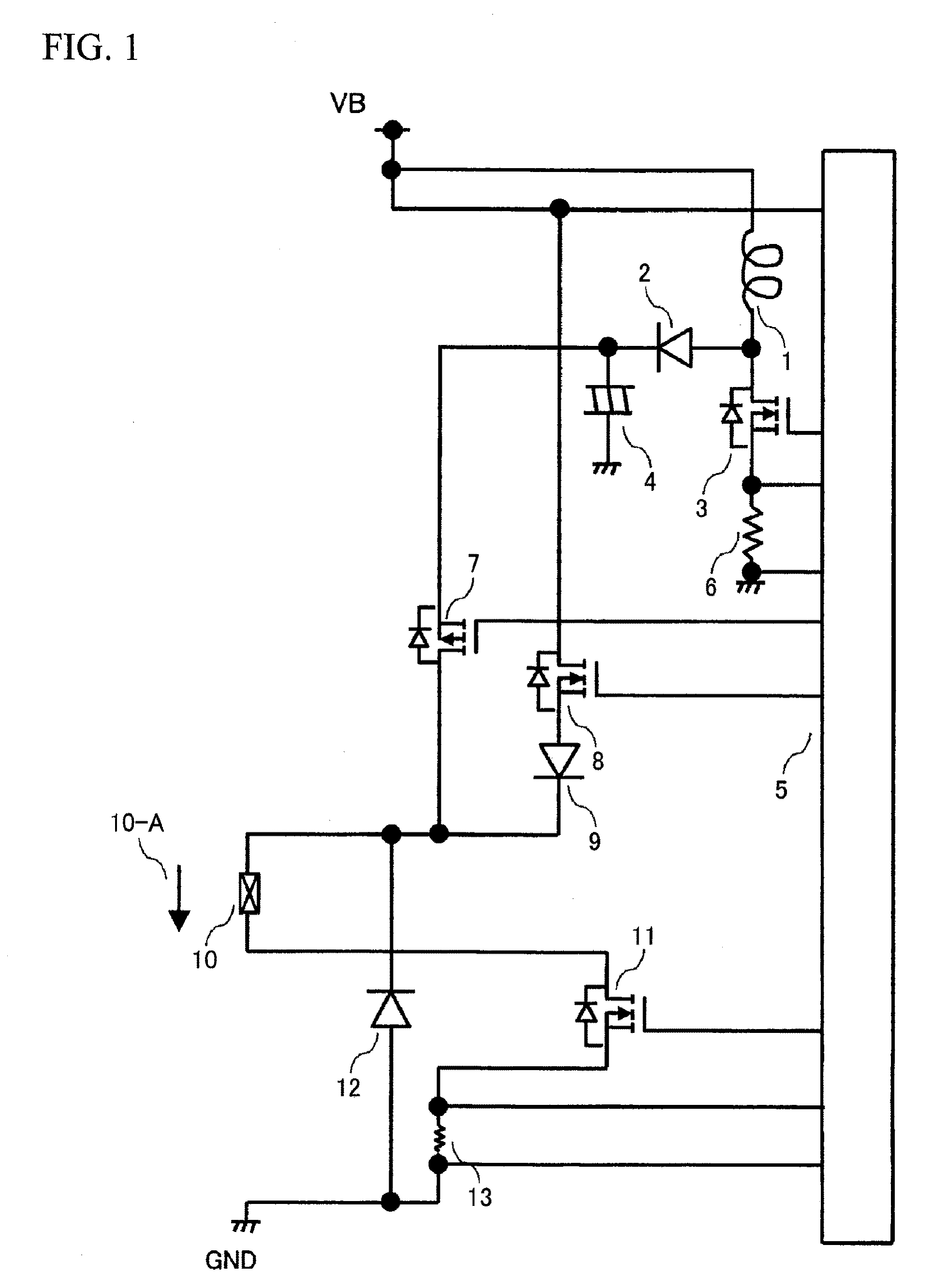
[0037]FIG. 4 shows a circuit diagram of Embodiment 1 of the present invention. In this circuit, a boost circuit is constituted by an injector controller 14, a boost coil 15, a diode 16, a switching MOSFET 17, an electrolytic capacitor 18 and a current detecting resistor 20. This boost circuit is designed to boost a battery voltage VB which is supplied from an external component. A high voltage VH that has been boosted by the boost coil 15 is applied to the upstream side of a peak current MOSFET 21 and the downstream side of this MOSFET 21 is connected with the anode side of a reverse current-preventing diode 24. The cathode side of the reverse current-preventing diode 24 is connected with an injector solenoid coil 25.
[0038]To the upstream side of a holding current MOSFET 22 is applied a battery voltage VB which is supplied from an external component and the downstream side of the holding current MOSFET 22 is connected with the anode side of a reverse current-preventing diode 23. The...
embodiment 2
[0046]FIG. 7 shows a circuit diagram of Embodiment 2 of the present invention. In this circuit, a boost circuit is constituted by an injector controller 49, a boost coil 36, a diode 37, a switching MOSFET 38, an electrolytic capacitor 39 and a current detecting resistor 41. This boost circuit is designed to boost a battery voltage VB to be supplied from an external component. A high voltage VH that has been boosted by the boost coil 36 is applied to the source side of a peak current MOSFET 42 and the drain side of this MOSFET 42 is connected with the anode side of a reverse current-preventing diode 45. The cathode side of the reverse current-preventing diode 45 is connected with an injector solenoid coil 47.
[0047]To the drain side of a holding current MOSFET 43 is applied a battery voltage VB which is supplied from an external component and the source side of the holding current MOSFET 43 is connected with the anode side of a reverse current-preventing diode 44. The cathode side of ...
embodiment 3
[0053]FIG. 10 shows a circuit diagram of Embodiment 3 of the present invention. In this circuit, a boost circuit is constituted by an injector controller 70, a boost coil 65, a diode 66, a switching MOSFET 67, an electrolytic capacitor 68 and a current detecting resistor 69. This boost circuit is designed to boost a battery voltage VB which is supplied from an external component. A high voltage VH that has been boosted by the boost coil 15 is applied to the source side of a peak current MOSFET 72 and the drain side of this MOSFET 72 is connected with the anode side of a reverse current-preventing diode 74. The cathode side of the reverse current-preventing diode 74 is connected in parallel with injector solenoid coils 78 and 79.
[0054]To a holding current MOSFET 71 is applied a battery voltage VB which is supplied from an external component and the source side of the holding current MOSFET 71 is connected with the anode side of a reverse current-preventing diode 73. The cathode side ...
PUM
 Abstract
Description
Claims
Application Information