
Sticky dilatation balloon and methods of using

a dilatation balloon and stick technology, applied in the field of medical devices for preventing embolization, can solve the problems of tissue debris or emboli trapped on the surface of the balloon, and achieve the effects of reducing the risk of embolism

Inactive Publication Date: 2009-04-30
SPECIALIZED VASCULAR TECH
View PDF50 Cites 95 Cited by
  • Summary
  • Abstract
  • Description
  • Claims
  • Application Information

AI Technical Summary

Benefits of technology

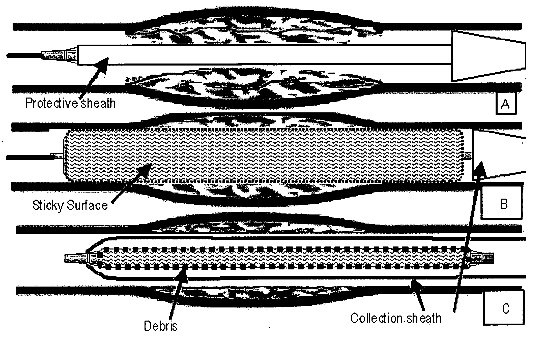
[0017]In a procedure, before stenting, the dilatable Sticky Balloon is collapsed in a smooth restraining sheath and advanced across the lesion. The restraining sheath is then pulled back to expose the balloon. The balloon is inflated to dilate the lesion. Dilatation causes pressure within the balloon to force the sticky outer surface directly into debris as it proceeds into apposition against the inner wall of a vessel. Tissue debris or emboli are trapped on the surface of the balloon. Loosened (i.e. pedunculated) tissue particles that are still connected to the inner vessel walls will also attach to the sticky surface. When the balloon is subsequently moved or deflated the adhesive or grasping strength holding particles to the surface is strong enough to detach their corporeal connections from the roots. Collecting loose particles from the vessel walls in this manner prevents the later inadvertent severance of particles which could lead to embolization when a severed particle becomes lost free floating and then lodged. After deflating the balloon it is pulled back into an expandable tube connected to the collection sheath.
[0019]Although the balloon itself provides dilatation, as an alternative to the sticky surface existing directly on the balloon the adhesion or material-grabbing function can also be provided by an expandable sheath over the dilatation balloon instead of it being on the balloon itself. For example, a thick biochemical adhesive composition and / or a complicated surface geometry / topography pattern for mechanical abrasion may be disposed on an outer sheath covering the balloon walls. This separation of the dilation and adhesion functions permits a greater degree of specialization and refinement without compromise of the materials chosen for the balloon walls and outer sheath. For example, to provide better dilation and safely withstand greater pressures within (without the risk of a bursting rupture), the balloon walls may be formed of a thicker material without worrying about the flexibility of the material (for better tissue-grabbing maneuverability) or the ability of an adhesive coating to be integrated therein. Rather, these criteria for material selection (i.e. flexibility, ability to bond to an adhesive coating, etc.) are made a priority for the outer sheath material.
[0020]Another advantage of delegating the function of tissue-grabbing to the sheath when using a mechanically abrasive structure is that it avoids making the fluid-filled balloon wall more susceptible to rupture. Etching or patterning methods used to produce a tissue-grabbing surface geometry (including the creation of microhooks, indentations, mesh, etc.) may at the same time weaken the strength of the surface material. By providing the tissue-grabbing surface on an outer sheath the strength of the balloon walls is not compromised while the sheath (potentially with an intricate tissue-grabbing design) remains protected from high pressures by the balloon walls.
[0021]In a preferred embodiment of the present invention the sticky dilatation balloon is dumbbell-shaped to trap the debris better. An extension of this concept is for the catheter upon which the main lesion-traversing balloon is mounted to incorporate additional balloons for deployment distal and proximal to the lesion. These outer balloons are preferably occlusion balloons for obstructing blood flow around the lesion to prevent embolization while the center sticky dilatation balloon is placed. The outer occlusion balloons also expedite and facilitate the trapping of debris to the surface of the center sticky balloon by preventing debris from leaving the area of the lesion.
[0023]The sticky dilatation balloon of the present invention may be obtained as an individual component for use with pre-existing standard catheter systems. Preferably, the balloon is acquired with a complementary catheter as part of an angioplasty balloon catheter system. By simply inflating the balloon against the plaque, the system binds to the unstable plaque and collects it for removal through the catheter lumen. The balloon can be made flexible and with a sufficiently small profile in its deflated condition to be able to cross a tight lesion without disrupting plaque during the initial insertion. An additional embolic protection mechanism does not have to be deployed outside the lesion. Unstable plaque is removed directly from the vessel wall while free floating plaque is rounded up and condensed so that no potential emboli are left behind to cause subacute embolization. These preventative and proactive features of the present invention coupled with its ease of use (at any time before, during, or after stenting) make it particularly advantageous and an improvement over the reference art.

Problems solved by technology

Tissue debris or emboli are trapped on the surface of the balloon.

Method used


Image

  • Sticky dilatation balloon and methods of using
  • Sticky dilatation balloon and methods of using
  • Sticky dilatation balloon and methods of using

Examples


Embodiment Construction

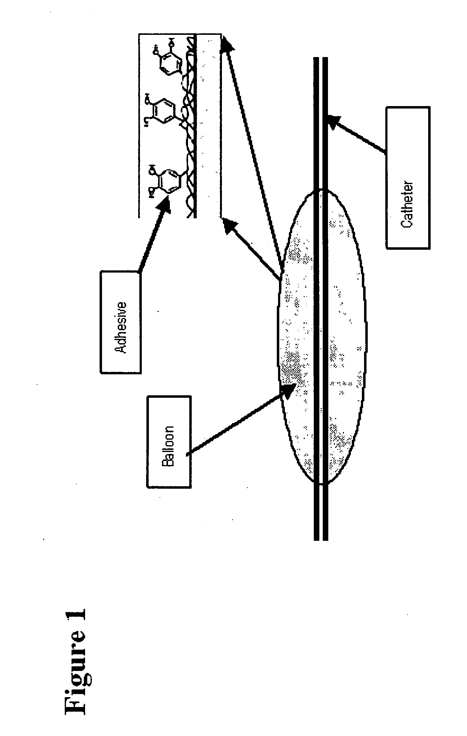
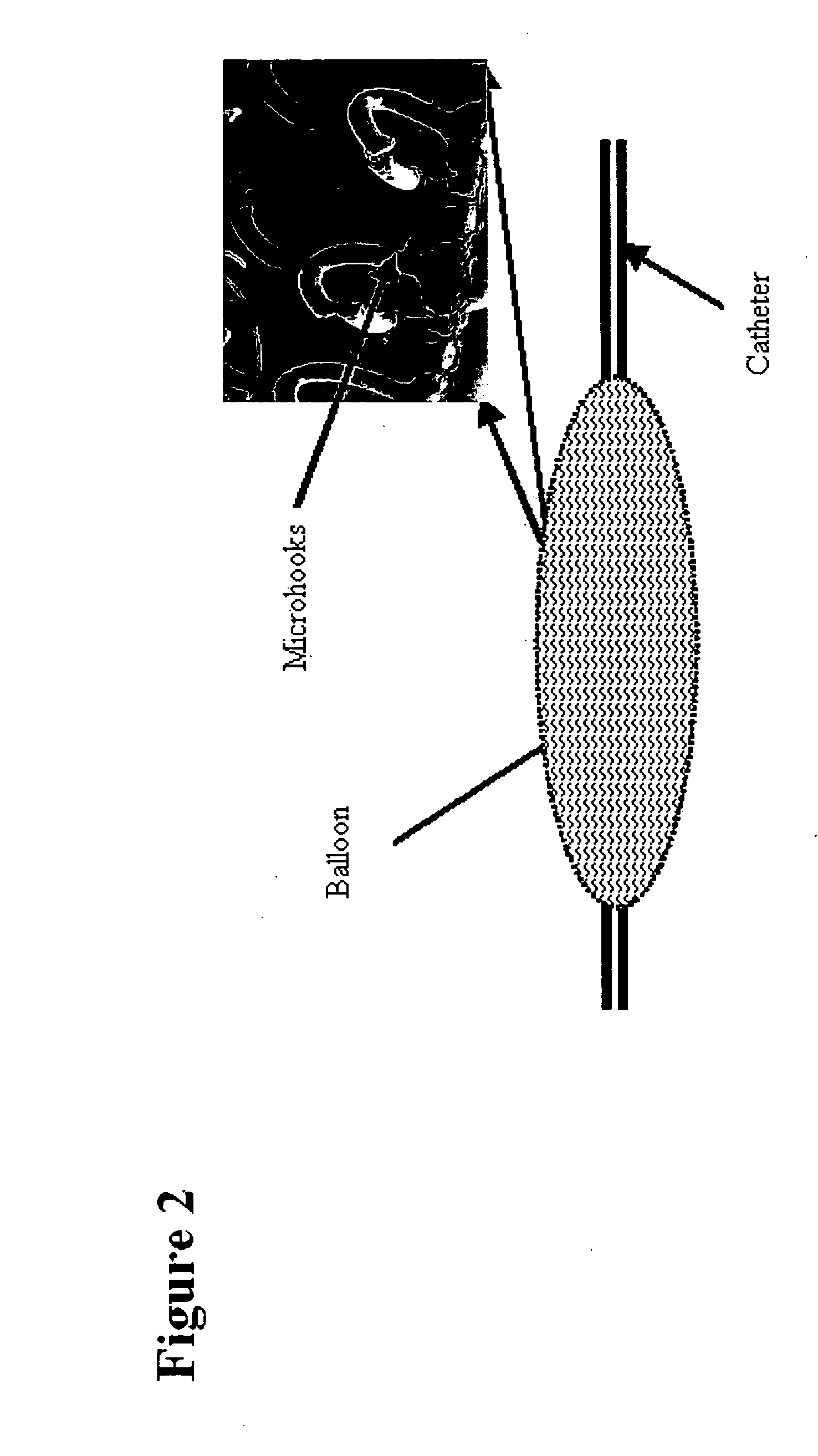
[0034]In accordance with the present invention, the preferred method for protecting against embolization in a stenting procedure is to use a sticky dilatation balloon with an outer surface that adheres to or grabs tissue debris and other extraneous materials. The balloon's outer surface can have a chemical bonded to it that adheres to unstable plaque substances such as lipids, cholesterol, thrombus, or calcium bits (see FIG. 1). Alternatively, the balloon can be covered with nano / microhooks (i.e. Velcro), nano / microfibers, hairs, split hairs, meshes, loops, foam, nano / microsuction cups, a soft or viscous gel layer, weaves, braids, aligned nano / microfibers, swirls, helical coils, nano / micro bumps, nano / micro pits, nano / micro jaws, or any other surface structure for trapping debris (see FIG. 2).

[0035]The emboli adhering / trapping surface can be part of the walls of an expandable element (i.e. inflatable balloon) or integrated onto a separate and distinct expandable cover (i.e. outer sh...


PUM


Abstract

The present invention involves an expandable element with an outer sticky surface. The expandable element may be in the form of a balloon with deflated and inflated configurations. The expandable element serves to both dilate a lumen in a blood vessel thereby opening it and to exert force upon the sticky surface in order to press it into apposition against a vessel wall. The outer sticky surface may be provided directly upon the expandable element or on a separate outer sheath that conforms to and follows the contours of the expandable element. The sticky surface may take the form of a biochemical composition and / or a mechanically abrasive structure such as microhooks, hairs, mesh netting, etc. Optionally, additional expandable elements may be provided proximal and distal to the main element to occlude blood flow on either side of a lesion in order to better trap emboli for collection.

Description

BACKGROUND OF THE INVENTION[0001]1. Field of the Invention[0002]The present invention relates to the field of medical devices for preventing embolization characterized by the obstruction of blood flow in a vessel or organ by an embolus or undissolved foreign particle (i.e. thrombi, tissue fragments, clumps of bacteria, protozoan parasites, fat globules, or gas bubbles). More specifically, the invention relates to non-prosthetic, temporary treatment devices for reducing the risk of embolization at any stage of a stenting procedure. Most specifically, the invention relates to proactive, expandable devices with debris-grabbing adhesive surfaces and their methods of use.[0003]2. Description of the Related Art[0004]Presently, embolic protection devices are used for procedures that entail a high risk of embolization with adverse consequences. These procedures include carotid artery stenting (CAS), renal artery stenting (RAS), and vein graft stenting (VGS). General approaches include dista...

Claims


Application Information

Patent Timeline
Patent Type & Authority Applications(United States)
IPC IPC(8): A61B17/221A61B17/22
CPCA61M25/1027A61M25/104A61M2025/109A61M2025/1086A61M2025/1088A61M2025/1081A61B17/22032A61B2017/00858A61B2017/00951A61B2017/22034A61B2017/22061A61B2017/22079A61B2017/00982
Inventor TO, JOHN THAO
Owner SPECIALIZED VASCULAR TECH
Learn More