Apparatus and Method for Detection of Radiation

a radiation detection and apparatus technology, applied in the field of apparatus and methods for radiation detection, can solve the problems of cs-137, sr-90, co-60, and cs-137 being more dangerous than others for this application, and requiring expensive installation of such a network of radiation sensors

Active Publication Date: 2009-05-07
IMAGE INSIGHT
View PDF13 Cites 26 Cited by
  • Summary
  • Abstract
  • Description
  • Claims
  • Application Information

AI Technical Summary

Benefits of technology

[0017]In another embodiment of the present invention, the imager contains a thin square of pixels. The likelihood of a high energy particle striking the thin square of pixels is at a maximum (maximum flux) when the thin square of pixels is perpendicular to the source of the high energy particles. The likelihood of a high energy particle striking the thin square of pixels decreases as the imager is panned and/or tilted away from the source or the source moves through the imagers field of view. In certain embodiments, the processor is able to perform a gradient search to determine the maximum flux by driving the movement of one or more imagers until maximum flux is reached. In yet other embodiment, several imagers perform a gradient search concurrently. The processor can then reference each imager and compare the photographic and or video images obtained from the imagers to determine the likely source of the high energy particles as the area where the images intersect. The imagers are preferably interconnected.
[0018]The movement of a source of high en

Problems solved by technology

However, the installation of such a network of radiation sensors would be costly and delay the readiness of the system.
However, some radioisotopes, for example Cs-137, Sr-90, or Co-60 are more dangerous than others for this application.
Dirty bombs would be economically devastating to a region due to the hig

Method used


Image

  • Apparatus and Method for Detection of Radiation
  • Apparatus and Method for Detection of Radiation
  • Apparatus and Method for Detection of Radiation

Examples


example 1

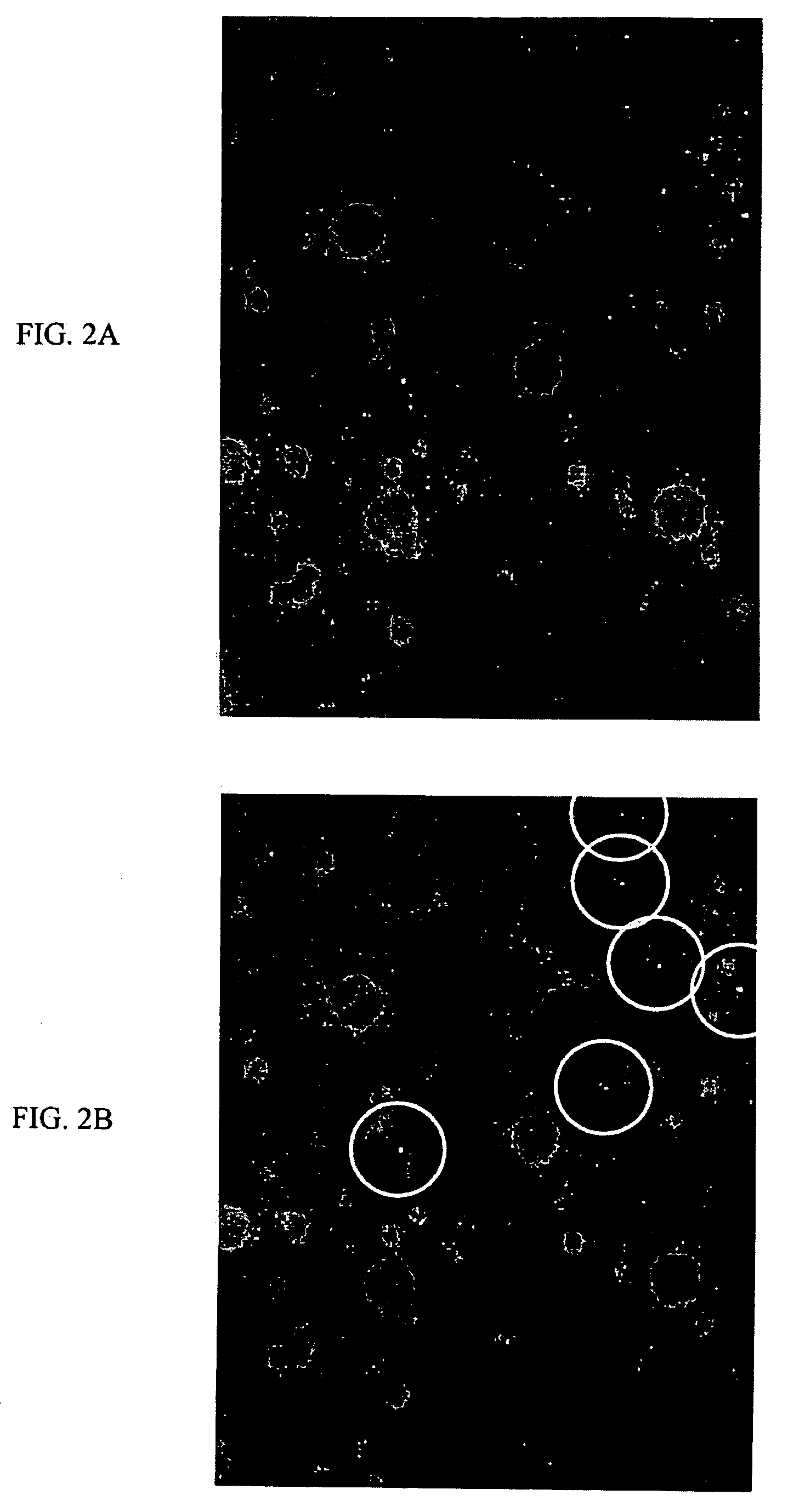
[0093]This example illustrates the ability of an imager to detect high energy particles and illustrates the sensitivity of the detector.

[0094]The functionality and sensitivity of the various imagers to detect gamma rays (still and video) from different manufacturers were performed. In each experiment, the cameras were operated, without modifications, according to their standard directions. Exposures were alternately made with and without radioactive material near the camera body. The images taken without a nearby source served as control experiments. In general, it was expected that very few of the control experiment images should display the small pixel-scale dots caused by radiation strikes on the detector. It is also reasonable to expect some, but not necessarily all, of the images (also called frames, exposures or collectively data) to contain such artifacts.

[0095]In one series of laboratory tests, a digital video camera manufactured by Logitech, specifically, the Quickcam for N...

example 2

[0107]This prophetic example illustrates the use of a CCD or CMOS camera or video camera to detect gamma-rays from a radioactive material.

[0108]One or more CCD or CMOS imagers may be used to sample a region or objects in the environment to determine if radioactive materials are present. An image from each of the cameras may have the charge at each pixel determined using the imager's hardware to detect pixels with high charge caused by photoelectrons generate by gamma rays. Alternatively, the image may be analyzed using software or firmware from the camera or a central processor connected to the camera to detect gamma-ray artifacts. The data signature of a gamma ray may include one or more pixels having high charge or brightness above a background or threshold level. The charge, brightness and frequency of the pixels struck by the gamma rays emitted from a source or radioactive material is expected to be greater than the charge or brightness for the same pixels interacting with ambie...

example 3

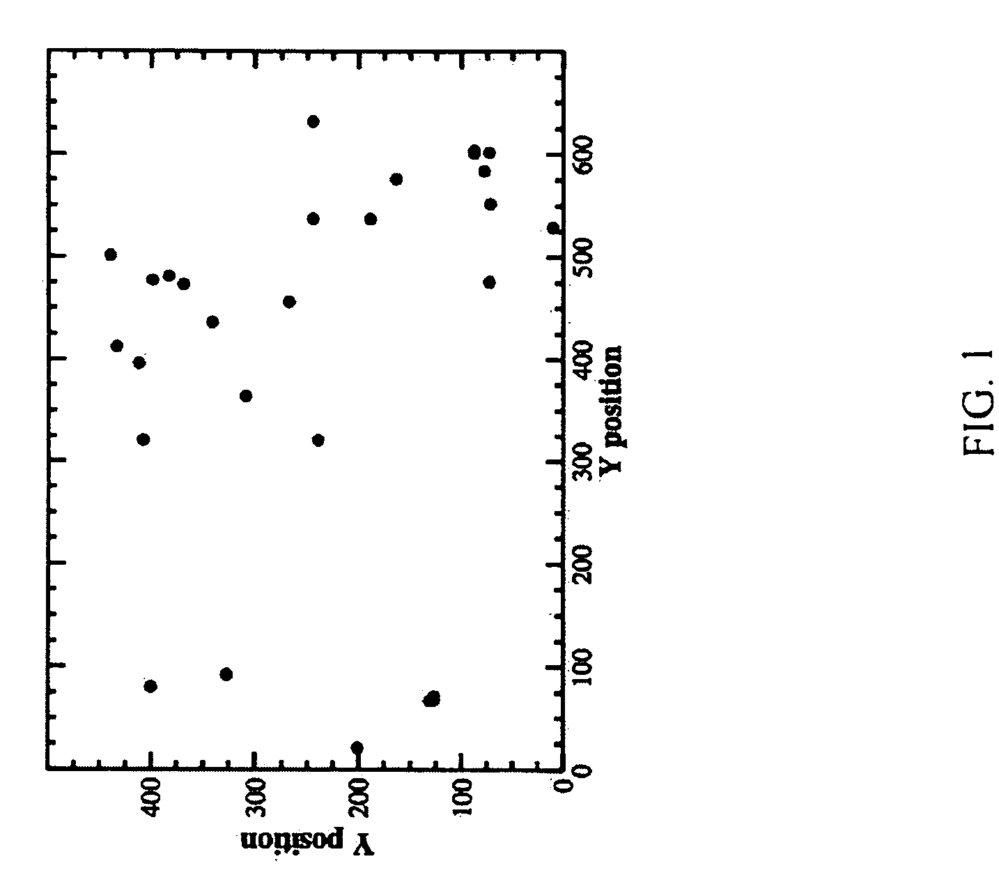
[0112]One non-limiting way of checking the pixels or image from an imager is to evaluate the four closest pixels (4CP) in digital image data. If the pixel or image data point under consideration is (X,Y), then the 4CP are: (X+1,Y), (X,Y+1), (X−1,Y), and (X,Y−1). The local background value of the imager can be taken as the average of the eight pixels corresponding to (X-2,Y−2), (X,Y−2), (X+2,Y−2), (X−2,Y), (X+2,Y), (X−2,Y+2), (X,Y+2), (X+2,Y+2); alternatively if a known reference object is in the field, it may be set to be the background and the average of the pixels or data points corresponding to the object set to the background.

[0113]In one mode of operation as illustrated in FIG. 7, a digital camera / digital video camera takes a picture (704) and in another step the digital image(s) may be transmitted to computer (708). The images may be searched for specific signatures of gamma-ray strikes and may also include false positive tests (712). If evidence of a radioactive material is f...


PUM


Abstract

Digital images or the charge from pixels in light sensitive semiconductor based imagers may be used to detect gamma rays and energetic particles emitted by radioactive materials. Methods may be used to identify pixel-scale artifacts introduced into digital images and video images by high energy gamma rays. Statistical tests and other comparisons on the artifacts in the images or pixels may be used to prevent false-positive detection of gamma rays. The sensitivity of the system may be used to detect radiological material at distances in excess of 50 meters. Advanced processing techniques allow for gradient searches to more accurately determine the source's location, while other acts may be used to identify the specific isotope. Coordination of different imagers and network alerts permit the system to separate non-radioactive objects from radioactive objects.

Description

CROSS-REFERENCE TO RELATED APPLICATIONS[0001]The application claims priority from U.S. Provisional Application No. 60 / 656,980 entitled, “APPARATUS AND METHOD FOR DETECTION OF RADIATION” filed Feb. 28, 2005 and U.S. application Ser. No. 11 / 364,027 entitled, “APPARATUS AND METHOD FOR DETECTION OF RADIATION” filed Feb. 28, 2006 both of which are hereby incorporated by reference in their entireties.PARTIES TO A JOINT RESEARCH AGREEMENT[0002]The United States Government may have certain rights to this invention pursuant to work funded thereby at the TRANSIT RESEARCH BOARD (TURB) OF THE NATIONAL ACADEMY OF SCIENCES under grants from IDEA Grant No. TRANSIT-42.INCORPORATION BY REFERENCE OF MATERIAL SUBMITTED ON A COMPACT DISC[0003]Not applicableBACKGROUND[0004]1. Field of Invention[0005]Not applicable[0006]2. Description of Related Art[0007]The ability to detect the unauthorized transportation of radioactive materials would be facilitated by a large-scale network of radiation sensors. Howev...

Claims


Application Information

Patent Timeline
IPC IPC(8): G01T1/00
CPCG01T1/11G01T1/366G01T7/00
Inventor RUBENSTEIN, ERIC P.
Owner IMAGE INSIGHT
Why Eureka
Try Eureka